
Image recording material

a technology of image recording and recording material, which is applied in the field of image recording material, can solve the problems of increasing the solubility of the image portion, deteriorating image sharpness, and insufficient contrast of images developed after exposure, and achieves high alkali solubility, low resolution, and high sensitization

Inactive Publication Date: 2005-06-30
FUJIFILM HLDG CORP +1
View PDF4 Cites 5 Cited by
  • Summary
  • Abstract
  • Description
  • Claims
  • Application Information

AI Technical Summary

Benefits of technology

[0023] The photosensitive / heat sensitive layer of the image recording material of the invention may have a single layer structure as well as a multilayer structure. In the case of the recording layer with a multilayer structure, (C) the specific compound, which is a characteristic component of the invention, may be contained in any layer of the multilayer structure. However, the compound is preferably contained in the alkali developer soluble first layer formed between a support and the layer sensitive to infrared laser, in terms of the effect of the invention.
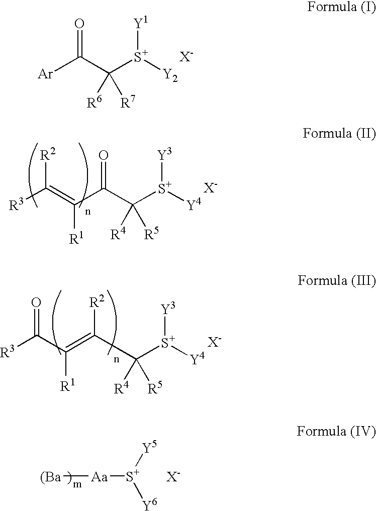
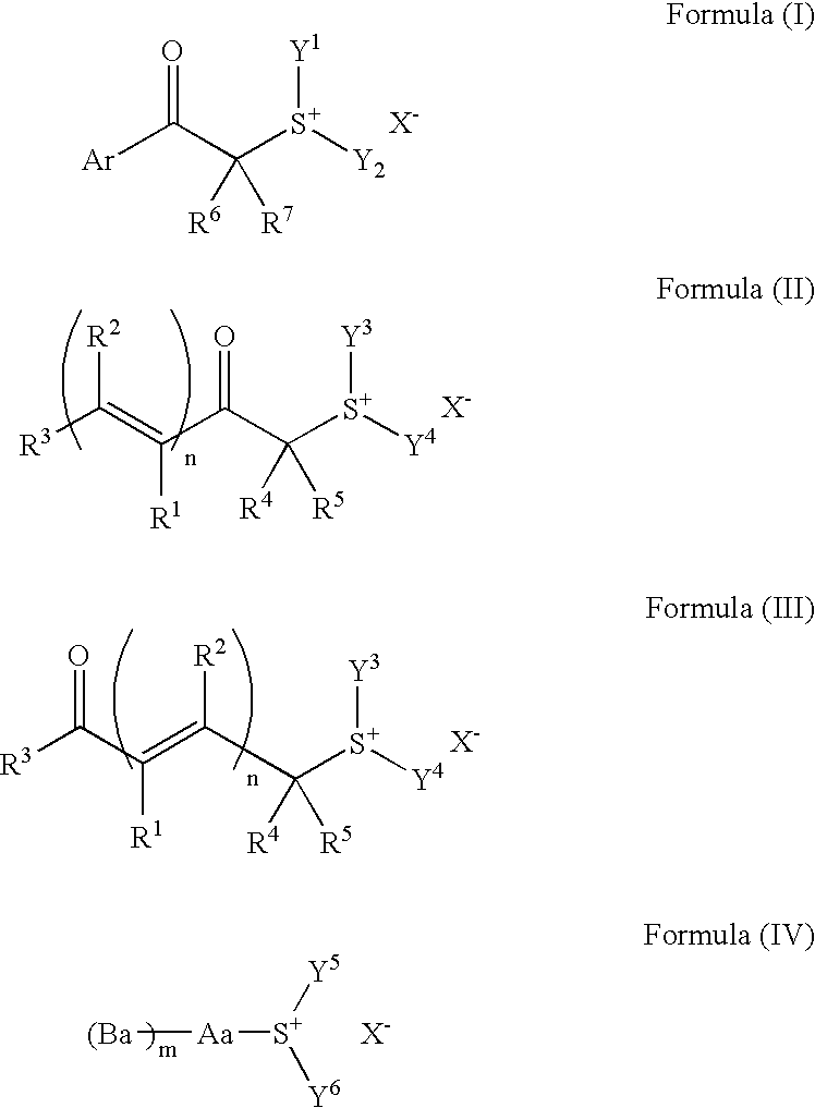
[0024] (C) The specific compound, which is a characteristic component of the invention, is at least one compound selected from a group of compounds defined by the formulae (I), (II), (III), and (IV). Hereinafter the respective compounds will be described in details.
[0025] At first, the compound defined by the formula (I) will be described.
[0026] In the formula (I), Ar represents an aryl or an aromatic group containing a hetero atom; R6 represents a hydrogen atom, a cyano group, an alkyl, or an aryl; R7 represents an alkyl or an aryl; Y1 and Y2 may be same as or different from each other and independently represent an alkyl, an aryl, an aralkyl, or an aromatic group containing a hetero atom; Y1 and Y2 may be bonded to each other to form a ring; Ar and at least one of Y1 and Y2 may be bonded to form a ring; Ar and R6 may be bonded to form a ring; the compound may comprise two or more groups defined by the formula (I) bonded together through linking groups at the positions of Ar, R6 or R7 or at the positions of Y1 or Y2; and X− represents a non-nucleophilic anion.
[0027] The compound defined by the formula (I) is preferably a compound defined by the following formula (Ia): wherein R11 to R15 may be same as or different from one another and independently represent a hydrogen atom, a nitro group, a halogen atom, an alkyl, an alkoxy, an alkyloxycarbonyl, an aryl or an acylamino group; at least two of R11 to R15 may be bonded to form a ring structure; R6 represents a hydrogen atom, a cyano group, an alkyl, or an aryl; R7 represents an alkyl or an aryl; Y1 and Y2 may be same as or different from each other and independently represent an alkyl, an aryl, an aralkyl, or an aromatic group containing a hetero atom; Y1 and Y2 may be bonded to each other to form a ring; at least one of R11 to R15 and at least one of Y1 and Y2 may be bonded to form a ring; at least one of R11 to R15 and R6 may be bonded to form a ring; the compound may comprise two or more groups defined by the formula (Ia) bonded together through linking groups at the positions of R11 to R15, R6 or R7 or at the position of Y1 or Y2; and X− represents a non-nucleophilic anion.
[0028] The formula (I) and the formula (Ia) will be described more in details.

Problems solved by technology

However, known photosensitive compositions used as recording layers of known thermal positive type planographic printing plate precursors have insufficient difference of the solubility to developers between exposed portions and non-exposed portions (solubility discrimination) and excess development or defective development attributed to variation of conditions of use is easily caused and accordingly, problems often results where the contrast of images developed after exposure becomes insufficient.
However, whilst the phenolic hydroxyl-containing compounds improve the removability (solubility) of the non-image portions to alkaline developers, on the other hand, the compounds also, at the same time, increase the solubility of the image portions.
This means that the sharpness of images deteriorates and this tendency is particularly noticeable in the case of thin lines and dotted image regions with low density coverage.

Method used


Image

  • Image recording material
  • Image recording material
  • Image recording material

Examples


examples

[0349] Hereinafter, the present invention will be described in more details along with Examples, however the invention is not limited to these Examples. In the Examples, image recording materials of the invention were evaluated by being used as planographic printing plate precursors. These evaluations were used as evaluations of the image recording materials of the invention.

[Production of Supporting Bodies]

[0350] A support is produced by treating JIS-A-1050 aluminum sheets with 0.3 mm thickness by a combination of the following processes.

(a) Mechanical Surface Roughening Treatment

[0351] While a suspension containing a polishing agent (silica sand) with a specific gravity of 1.12 and water is supplied as a polishing slurry to a surface of each aluminum sheet, and mechanical surface roughening is carried out by rotating roller type nylon brushes. The average particle size of the polishing agent is 8 μm and maximum particle size 50 μm. The material of the nylon brushes is 6-10 ny...


PUM

PropertyMeasurementUnit
wavelength rangeaaaaaaaaaa
particle sizeaaaaaaaaaa

Abstract

A positive image recording material applicable to infrared laser comprising a support whereon is formed a photosensitive / heatsensitive layer containing (A) an alkali-soluble resin, (B) a photothermal conversion substance, and (C) at least one compound selected from a group of compounds defined by the formulae (I), (II), (III), and (IV) exhibiting improved solubility to an alkaline developer following exposure with an infrared laser wherein the substituent groups of the formulae (I) to (IV) are specified in the specification for this invention.

Description

CROSS-REFERENCE TO RELATED APPLICATION [0001] This application claims priority under 35 USC 119 from Japanese patent application, No. 2003-433712, the disclosure of which is incorporated by reference herein. BACKGROUND OF THE INVENTION [0002] 1. Field of the Invention [0003] The present invention relates to an image recording material, provided on a support and comprising a photosensitive / heat sensitive layer with improved solubility to an alkaline developer by exposure. More particularly it relates to a so-called direct plate-making positive image recording material usable for direct plate-making by scanning a laser beam with a high energy density, such as an infrared laser beam, based on digital signals from a computer or the like. [0004] 2. Description of the Related Art [0005] Lasers have advanced remarkably recently, and especially compact and high powered solid lasers and semiconductor laser, having light emissions in the near infrared to infrared regions, have become readily ...

Claims


Application Information

Patent Timeline
Patent Type & Authority Applications(United States)
IPC IPC(8): B41C1/10G03F7/004B41M5/36G03F7/00G03F7/11
CPCB41C1/1008B41C2210/262G03F7/0045Y10S430/106Y10S430/11Y10S430/165Y10S430/111B41C2201/04B41C2201/12B41C2201/14B41C2210/02B41C2210/06B41C2210/14B41C2210/20B41C2210/22B41C2210/24B41C1/1016
Inventor WATANABE, KOTAROKUNITA, KAZUTOKODAMA, KUNIHIKO
Owner FUJIFILM HLDG CORP
Learn More