Planographic printing plate precursor

Active Publication Date: 2005-09-01
FUJIFILM HLDG CORP +1
View PDF2 Cites 4 Cited by
  • Summary
  • Abstract
  • Description
  • Claims
  • Application Information

AI Technical Summary

Benefits of technology

[0020] The dispersion phase such as the above, may be formed, for example, by the following methods: (1) a method in which two types of resins which are incompatible with each other are used in combination, or (2) a method in which a granular polymer, selected from a microcapsule or a latex, is dispersed in a matrix resin.
[0021] Because a system utilizing a change in solubility of the recording layer in aqueous alkali is used in the planographic printing plate precursor of the invention, a resin used in the positive recording layer which contains a water-insoluble and aqueous alkali-soluble resin is a preferred aspect.
[0022] In the invention, the method (1), in which two types of resins which are incompatible with each other are used in combination to form a dispersion phase, is preferable from the viewpoint of ease of production. Resins which are incompatible with each other may be selected as these two types of resins. Also, the two types of resins may be those which are dissolved uniformly in a coating solvent, or those which form a dispersion phase along with removal of a solvent when the recording layer is formed.
[0023] Also, the lower recording layer such as above is preferably one in which among the aforementioned resins, the resin forming a matrix comprises a macromolecular compound, which is insoluble in water and soluble in an aqueous alkali solution, and the above dispersion phase contains a compound which generates an acid or a radical by ir

Problems solved by technology

On the other hand, in its exposed portions (non-image portions), interaction of the infra red dye with the binder resin is weakened by the heat generated.
However, insofar as such infrared-laser-applicable positive planographic printing plate precursor materials are concerned, differences in the degree of resistance against dissolution in a developer between unexposed portions (image portions) and exposed portions (non-image portions) therein, that is, differences in development latitude have not yet been sufficient under various conditions of use.
Thus, problems have occurred insofar that, with changes in conditions of use of materials, materials have tended to be either excessively developed or inadequately developed.
As a result, the plate precursor has problems in that the printing resistance thereof deteriorates and the ink-acceptability thereof worsens.
Such problems stem from fundamental differences in plate-making mechanisms between infrared-laser-applicable positive type planographic printing plate precursor materials and positive type planographic printing plate precursor materials from which printing

Method used


Image

  • Planographic printing plate precursor
  • Planographic printing plate precursor
  • Planographic printing plate precursor

Examples


examples

[0255] The invention will be explained by way of examples, which, however, do not limit the scope of the invention.

examples 1 to 3

(Production of a Substrate)

[0256] An aluminum alloy having the following composition was used to prepare a molten bath: Si: 0.06 mass %, Fe: 0.30 mass %, Cu: 0.014 mass %, Mn: 0.001 mass %, Mg: 0.001 mass %, Zn: 0.001 mass % and Ti: 0.03 mass %, wherein the balance was Al and unavoidable impurities. The molten bath was subjected to molten bath treatment and filtered to produce an ingot having a thickness of 500 mm and a width of 1200 mm by a Direct Chill (DC) casting method. The surface of the ingot was scalped using a scalping machine to an average thickness of 10 mm. The ingot was then kept at 550° C. by heating it uniformly for about 5 hours and then, when the temperature was lowered to 400° C., the ingot was made into a rolled plate 2.7 mm in thickness by using a hot rolling mill. The rolled plate was further heat-treated at 500° C. by using a continuous annealing machine and then, cold-rolled to produce a finished 0.24-mm-thick aluminum plate. This aluminum plate was cut into...

examples 4 to 6

[0272] Planographic printing plate precursors 4 to 6 were obtained in the same manner as in Example 1, except that the lower recording layer coating solution was altered.

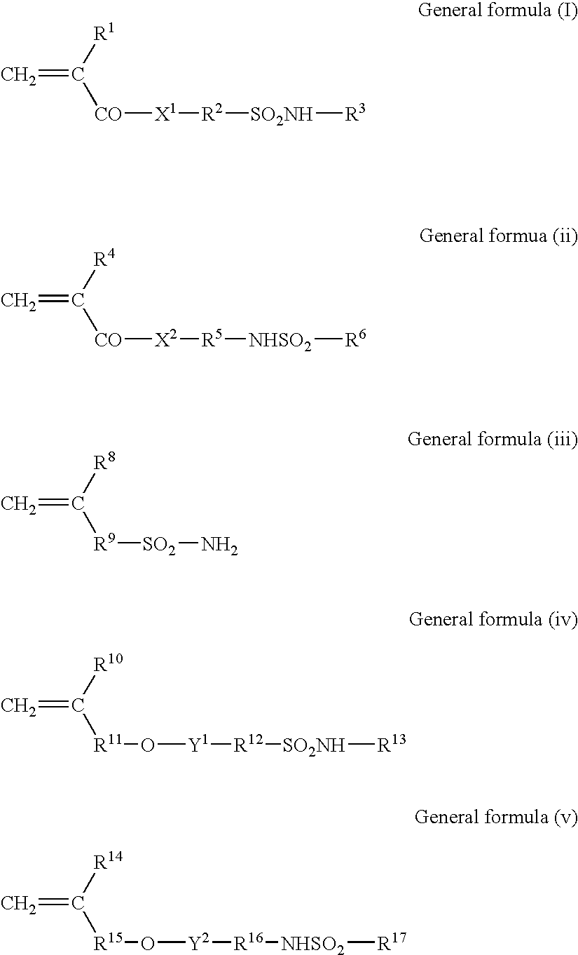
N-(4-(Amount described in Table 2,aminosulfonylphenyl)methacrylamide / D g)acrylonitrile / methylmethacrylate(36 / 34 / 30, weight average molecularweight: 100000, acid value: 2.65)PD-1 (following structure)(Amount described in Table 2,E g)Dye C (following structure)0.109 g4,4′-Bishydroxyphenylsulfone0.126 gTetrahydrophthalic acid anhydride0.190 gp-Toluenesulfonic acid(Amount described in Table 2,F g)3-Methoxy-4-0.030 gdiazodiphenylamine hexafluorophosphateCompound obtained by 0.10 gchanging the counter ion of Ethyl Violetto 6-hydroxynaphthalenesulfoneMethyl ethyl ketone25.36 g1-Methoxy-2-Propanol 13.0 gγ-butyrolactone 13.2 g

[0273]

TABLE 2Example 4Example 5Example 6C (g)1.9201.701.82D (g)0.1920.430.32E (g)0.1200.1230.130Dye CPD-1


PUM

PropertyMeasurementUnit
Sizeaaaaaaaaaa
Sizeaaaaaaaaaa
Massaaaaaaaaaa

Abstract

A planographic printing plate precursor comprises a support and two or more positive recording layers which are formed on the support, contain a resin and an infrared absorbing agent and exhibit an increase in solubility in an aqueous alkali solution by exposure to infrared laser light, wherein the positive recording layer closest to the support among these two or more positive recording layers contains at least two types of resins among which at least one type forms a dispersion phase. It is preferable that the dispersion phase be formed of (1) a high-polymer compound incompatible with a high-polymer matrix or (2) a granular polymer selected from a microcapsule and a latex, and contains an infrared absorbing agent and an acid generator.

Description

CROSS-REFERENCE TO RELATED APPLICATION [0001] This application claims priority under 35 USC 119 from Japanese Patent Application No. 2004-055240, the disclosure of which is incorporated by reference herein. BACKGROUND OF THE INVENTION [0002] 1. Field of the Invention [0003] The present invention relates to a planographic printing plate precursor. More specifically, the invention relates to an infrared-laser-applicable planographic printing plate precursor for a so-called CTP (Computer To Plate), from which a printing plate can be directly formed based on digital signals from a computer or the like. [0004] 2. Description of the Related Art [0005] The development of lasers for planographic printing in recent years has been remarkable. In particular, high-power, small-sized solid lasers and semiconductor lasers that emit near-infrared and infrared rays have become easily obtainable. These lasers are very useful as exposure light sources when forming printing plates directly from digita...

Claims


Application Information

Patent Timeline
IPC IPC(8): G03F7/004B41C1/10G03F7/00G03F7/26
CPCB41C1/10B41C1/1016B41C2201/04B41C2201/14B41C2210/262B41C2210/06B41C2210/14B41C2210/22B41C2210/24B41C2210/02
Inventor TASHIRO, HIROSHI
Owner FUJIFILM HLDG CORP
Why Eureka
Try Eureka