Thermoplastic resin pellet, process for preparing thermoplastic resin pellets and expanded thermoplastic resin bead

a thermoplastic resin and thermoplastic resin technology, applied in the field of thermoplastic resin pellets, process for preparing thermoplastic resin pellets and expanded thermoplastic resin beads, can solve the problems of known strand cutting method, inability to prepare resin pellets having a very small weight, and the need to run strands at an excessively high speed, etc., and achieve high efficiency

Inactive Publication Date: 2005-07-14
JSP CORP
View PDF11 Cites 34 Cited by
  • Summary
  • Abstract
  • Description
  • Claims
  • Application Information

AI Technical Summary

Benefits of technology

[0009] It is, therefore, an object of the present invention to provide an improved strand cut method which can prepare very small thermoplastic resin pellets with a high efficiency.
[0010] Another object of the present invention is to provide a strand cut method which can prepare very small thermoplastic resin pellets having a uniform size.
[0011] It is a further object of the present invention to provide thermoplastic resin pellets which have a uniform small size and which are suitable as raw materials for expanded beads and moldings.
[0019] It has been unexpectedly found that when a surfactant is contained in the water, the vibration of the strands can be prevented and the bonding of adjacent strands can be prevented. Although not wishing to be bound by the theory, it is inferred that the surface tension of water causes the vibration of strands entering the water and that the addition of the surfactant in the water decreases the surface tension of the water to minimize the vibration of the strands.

Problems solved by technology

The known strand cut method, however, has a problem because very small resin pellets having a very small weight cannot be prepared on a large scale.
If the known strand cut method is adopted to produce small resin pellets with a practically acceptable resin extrusion rate, then it will be necessary to run the strands at an excessively high speed and to increase the cutting speed of the cutter beyond its ability.
With the known strand cut method, therefore, it is not possible to produce small resin pellets having a uniform size in a stable manner.
While the UWC method may prepare small size pellets, the equipment costs are very high.
Additionally, not all thermoplastic resins can be pelletized by the UWC method.

Method used


Image

  • Thermoplastic resin pellet, process for preparing thermoplastic resin pellets and expanded thermoplastic resin bead
  • Thermoplastic resin pellet, process for preparing thermoplastic resin pellets and expanded thermoplastic resin bead
  • Thermoplastic resin pellet, process for preparing thermoplastic resin pellets and expanded thermoplastic resin bead

Examples


examples 1 to 7

[0083] Preparation of Resin Pellets:

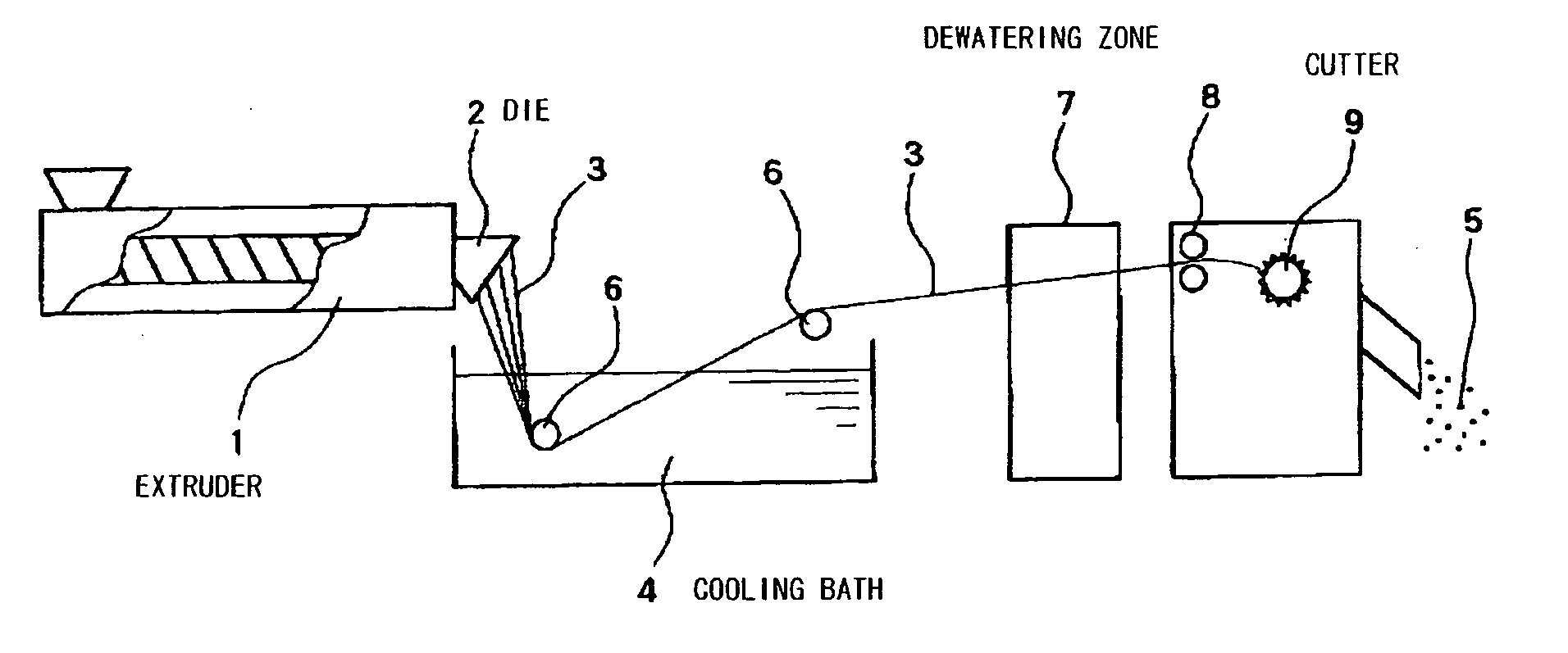
[0084] To an extruder, 100 parts of a propylene-ethylene random copolymer (ethylene content: 2.5%; melting point: 143° C.; MFR: 7 g / 10 min.) and 0.05 part of zinc borate powder (cell controlling agent) were fed and kneaded at 230° C. to obtain a melt. The extruder had a barrel diameter and a screw length as shown in Table 1 and had an outlet provided with a die having a multiplicity of orifices. The number, diameter and minimum distance between the peripheries of adjacent two orifices (inter-periphery distance) were as shown in Table 1. The melt was extruded through the entire orifices in the atmosphere in the form of strands. The strands were immediately introduced into a cooling bath maintained at 20° C. for quenching and solidification. The cooling bath was composed of 100 parts of water and 0.005 part of polyoxyethylene lauryl ether (nonionic surfactant) and was contained in a vessel having a length of 1 m, a width of 0.4 m and a height of 1 ...

example 8

[0092] Preparation of Resin Pellets:

[0093] To an extruder, 100 parts of a propylene-ethylene random copolymer (ethylene content: 2.5%; melting point: 143° C.; MFR: 7 g / 10 min.) and 0.05 part of zinc borate powder (cell controlling agent) were fed and kneaded at 230° C. to obtain a melt. The extruder had a barrel diameter of 6.5 cm and a screw length of 240 cm and had an outlet provided with a die having a multiplicity of orifices. The number, diameter and minimum distance between the peripheries of adjacent two orifices (inter-periphery distance) were as shown in Table 3. The melt was extruded through the entire orifices in the atmosphere in the form of strands. The strands were immediately introduced into a cooling bath maintained at 20° C. for quenching and solidification. The cooling bath was composed of 100 parts of water and 0.03 part of polyether-modified silicone oil (nonionic surfactant; SR8410 manufactured by Toray Dow Corning Silicone Co., Ltd.) and was contained in a ves...

example 9

[0097] Example 8 was repeated in the same manner as described except that the resin melt contained 1 part of carbon black (coloring agent), 3 parts of brominated flame retardant (Trade Name: FIRE GUARD FG-3100; manufactured by Teijin Chemical Co., Ltd.) and 1.5 parts of antimony trioxide (flame retardant aid) in addition to 100 parts of the propylene-ethylene random copolymer and 0.05 part of the zinc borate powder and that the orifice number, the discharge amount per one orifice and the amount of dry ice were changed as shown in Table 3. The results are summarized in Table 3. The apparent density and the calorific value of the high temperature peak of the expanded beads thus obtained indicate that they are suited for in-mold molding.

TABLE 3Examples89OrificeDiameter (mm)0.80.8of DieNumber272275Inter-peripheral11distance (mm)Amount of surfactant (part)0.030.03Extrusion rate W (kg / hr)7070Discharge amount per orifice M0.260.25(kg / hr)Discharge balance B (kg / (hr · cm2)1.661.66Average w...


PUM

PropertyMeasurementUnit
temperatureaaaaaaaaaa
weightaaaaaaaaaa
apparent densityaaaaaaaaaa

Abstract

A process for preparing thermoplastic resin pellets, including extruding a melt of a thermoplastic resin into a gas phase through a die in the form of strands, immersing the strands in a bath containing water and a surfactant to cool the strands, taking the cooled strands out of the bath, and cutting the taken-out strands into pellets.

Description

CROSS-REFERENCE TO RELATED APPLICATION [0001] This application claims, under 35 USC 119, priorities of Japanese Patent Application No. 2004-006063, filed Jan. 13, 2004, disclosures of which, inclusive of the specifications, claims and drawings, are hereby incorporated by reference herein. BACKGROUND OF THE INVENTION [0002] 1. Field of the Invention [0003] This invention relates to a process for preparing thermoplastic resin pellets, to a thermoplastic resin pellet obtainable by the process and to an expanded thermoplastic resin bead obtainable from the pellet. [0004] 2. Description of Prior Art [0005] In-mold foam moldings of a base resin containing a polystyrene-based resin or a polyolefin-based resin are widely used in various applications such as containers (e.g. fish boxes), packaging materials, impact energy absorbing materials (e.g. bumpers) and heat insulating materials because of their excellent softness and impact resisting properties. The foam moldings are generally produc...

Claims


Application Information

Patent Timeline
Patent Type & Authority Applications(United States)
IPC IPC(8): B29B9/06B29C44/34C08J3/22B29C48/30C08J3/12C08J9/16C08J9/18
CPCB29B9/06B29C44/3461Y10T428/2982C08J9/18C08J2203/06B29K2105/048B29C48/0022B29C48/05B29C48/919B29C48/345B29K2021/003B29C48/022
Inventor SASAKI, HIDEHIROHIRA, AKINOBUTOKIWA, TOMOO
Owner JSP CORP
Why Eureka
Try Eureka