Method and system for high speed measuring of microscopic targets

Inactive Publication Date: 2005-08-11
ELECTRO SCI IND INC
View PDF34 Cites 5 Cited by
  • Summary
  • Abstract
  • Description
  • Claims
  • Application Information

AI Technical Summary

Benefits of technology

[0026] A method of the present invention overcomes the limitations of the prior art imaging of non-cooperative targets by illuminating a surface with a scanning beam, acquiring data from at least one triangulation-based channel, and acquiring in parallel or

Problems solved by technology

Measurement of the diameter can be done with a camera system and appropriate illumination, but accuracy is often limited by light scattering and limited depth of focus when high magnification is required.
Unfortunately, triangulation systems are not immune to fundamental limitations like occlusion and sensitivity to background reflection.
Furthermore, at high magnification, the depth of focus can limit performance of systems, particularly edge location accuracy, when the object has substantial relief and a wide dynamic range (i.e. variation in surface reflectance).
However, narrow angle multiple reflections from the edge of the ball can corrupt the measurement and result in ambiguous edge locati

Method used


Image

  • Method and system for high speed measuring of microscopic targets
  • Method and system for high speed measuring of microscopic targets
  • Method and system for high speed measuring of microscopic targets

Examples


Embodiment Construction

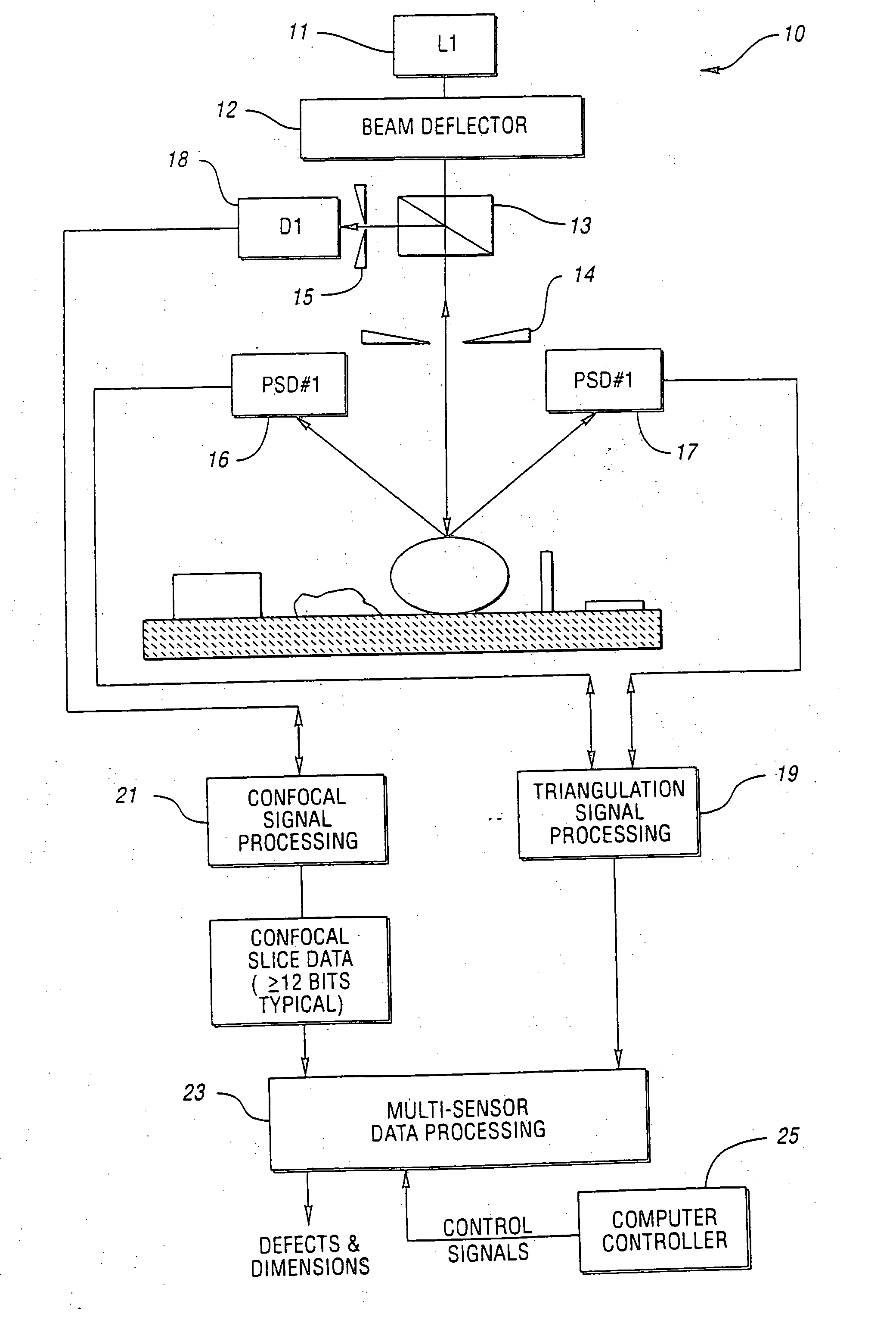
[0078]FIG. 9 is a simplified schematic view, without optical elements, of an integrated triangulation-confocal system, generally indicated at 10, constructed in accordance with the present invention. The system 10 includes a laser 11 (i.e. L1), a beam deflector 12 and a beam splitter assembly 13. The system 10 also includes a pair of spatial filters in the form of slits 14 and 15. The system 10 further includes first and second position sensitive detectors 16 and 17, respectively, and a photodiode detector 18. The detectors 16 and 17 provide triangulation analog signals to a triangulation signal processor 19 for triangulation signal processing and the detector 18 provides confocal analog signals to a confocal signal processor 21 for confocal signal processing. The resulting digital Z (i.e. height) and grey scale data from the processor 19 is combined with digital confocal slice data (≧12 bits typical) from the processor 21 by a data processor 23 which provides multi-sensor data proc...


PUM


Abstract

A system including confocal and triangulation-based scanners or subsystems provides data which is both acquired and processed under the control of a control algorithm to obtain information such as dimensional information about microscopic targets which may be “non-cooperative.” The “non-cooperative” targets are illuminated with a scanning beam of electromagnetic radiation such as laser light incident from a first direction. A confocal detector of the electromagnetic radiation is placed at a first location for receiving reflected radiation which is substantially optically collinear with the incident beam of electromagnetic radiation. The system includes a spatial filter for attenuating background energy. The triangulation-based subsystem also includes a detector of electromagnetic radiation which is placed at a second location which is non-collinear with respect to the incident beam. This detector has a position sensitive axis. Digital data is derived from signals produced by the detectors. In this way, data from at least one triangulation-based channel is acquired in parallel or sequentially with at least one slice of confocal image data having substantially perfect temporal and spatial registration with the triangulation-based sensor data. This allows for fusion or further processing of the data for use with a predetermined measurement algorithm to thereby obtain information about the targets.

Description

CROSS-REFERENCE TO RELATED APPLICATION [0001] This application is related to U.S. patent application entitled “Versatile Method and System for High Speed, 3D Imaging of Microscopic Targets” filed on the same day as this application.TECHNICAL FIELD [0002] This invention relates to methods and systems for high speed measuring of targets and, in particular, to methods and systems for high speed measuring of microscopic targets which may be “non-cooperative.”BACKGROUND ART [0003] 1. Recognition of Need [0004] A class of three-dimensional imaging and measurement applications now requires unprecedented demonstration of capability to support new microelectronic and micromechanical fabrication technologies. For example, emerging semiconductor fabrication technologies are directed toward establishing a high density of interconnection between the chip and package. The “bumped wafer” and miniature ball grid array (“μ-BGA”) markets are emerging, and large scale growth is predicted. For instance...

Claims


Application Information

Patent Timeline
IPC IPC(8): G01B11/02G01B11/24G01B11/25G01N21/95G02B21/22
CPCG01B11/026G01B11/24G02B21/22G01B11/2545G01N21/9501G01B11/2518
Inventor SVETKOFF, DONALD J.KILGUS, DONALD B. T.LIN, WARRENEHRMANN, JONATHAN S.
Owner ELECTRO SCI IND INC
Why Eureka
Try Eureka