Orthopaedic scaffolds for tissue engineering

a tissue engineering and orthopaedic technology, applied in the field of orthopaedic scaffolds for tissue engineering, can solve the problems of compromising bone strength, slow recovery time, and considerable patient discomfort, and achieve the effect of avoiding intricate molding processes and simple mixing

Inactive Publication Date: 2005-08-11
CANHAM LEIGH TREVOR +2
View PDF10 Cites 18 Cited by
  • Summary
  • Abstract
  • Description
  • Claims
  • Application Information

AI Technical Summary

Benefits of technology

[0027] Using the method of the invention, it is possible to obtain the larger scaffolds needed for most bone grafts with the desired nanostructure throughout. Furthermore, the scaffolds will have highly ordered structures. For bone grafts this translates into excellent control of macroporosity and macropore architecture
[0048] The stability of the assembled structure may also be improved by application of heat.

Problems solved by technology

Autografting is considered the gold standard in efficacy for procedures that require supplemental bone, but autograft harvest carries risks and considerable patient discomfort.
Recovery time is slow and often exceeds 6 months.
However the sterilization process may be compromise the strength of the bone, and there is a perceived risk of transmitting infectious disease.
A bone xenograft, in which processed bone from animals is transplanted to humans offers higher productivity but is perceived to be riskier than allografting in terms of disease transmission.
Many of the existing porous biodegradable polymeric systems have been found to have limitations for use as orthopaedic scaffolds for cell ingrowth.
For instance, it is often possible only to obtain a poor match of mechanical properties to the tissue being replaced.
There is difficulty in achieving uniform porosity over large distances within the polymeric system, and although matrices can be osteoconductive, they may not have any osteoinductive ability.
Porous ceramic systems also suffer from poor control over pore size distribution, and may also have poor moldability compared to polymers.
A significant limitation of nanostructuring silicon via electrochemistry is the inability to anodise across the depths needed for large implants.
There is however no disclosure as to how large channels for bone in-growth could be realized in such composites.

Method used


Image

  • Orthopaedic scaffolds for tissue engineering
  • Orthopaedic scaffolds for tissue engineering
  • Orthopaedic scaffolds for tissue engineering

Examples


example 1

Step 1

Synthesis of Individual Structures:

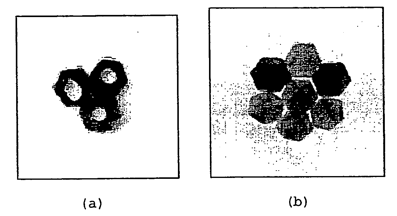
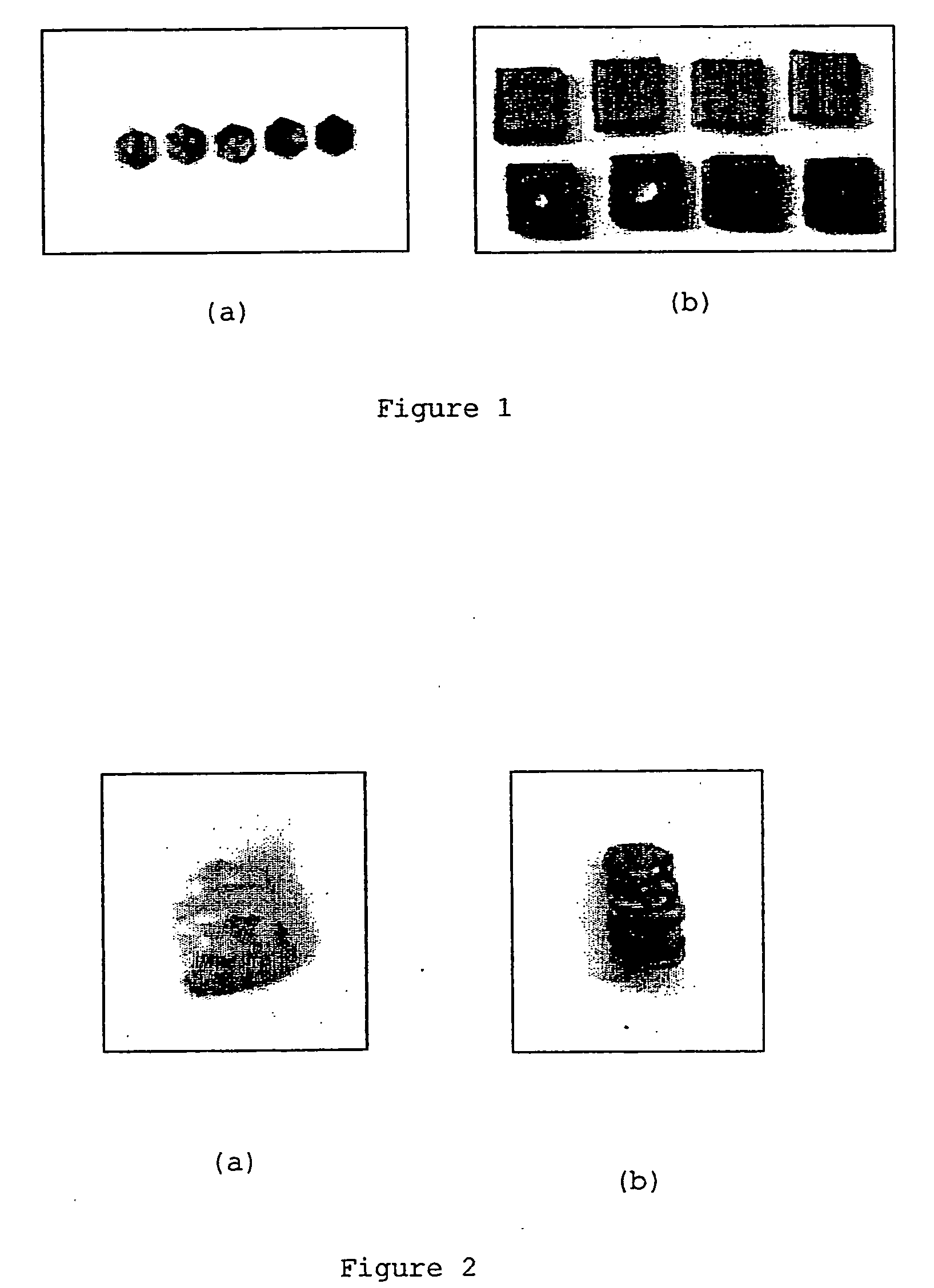
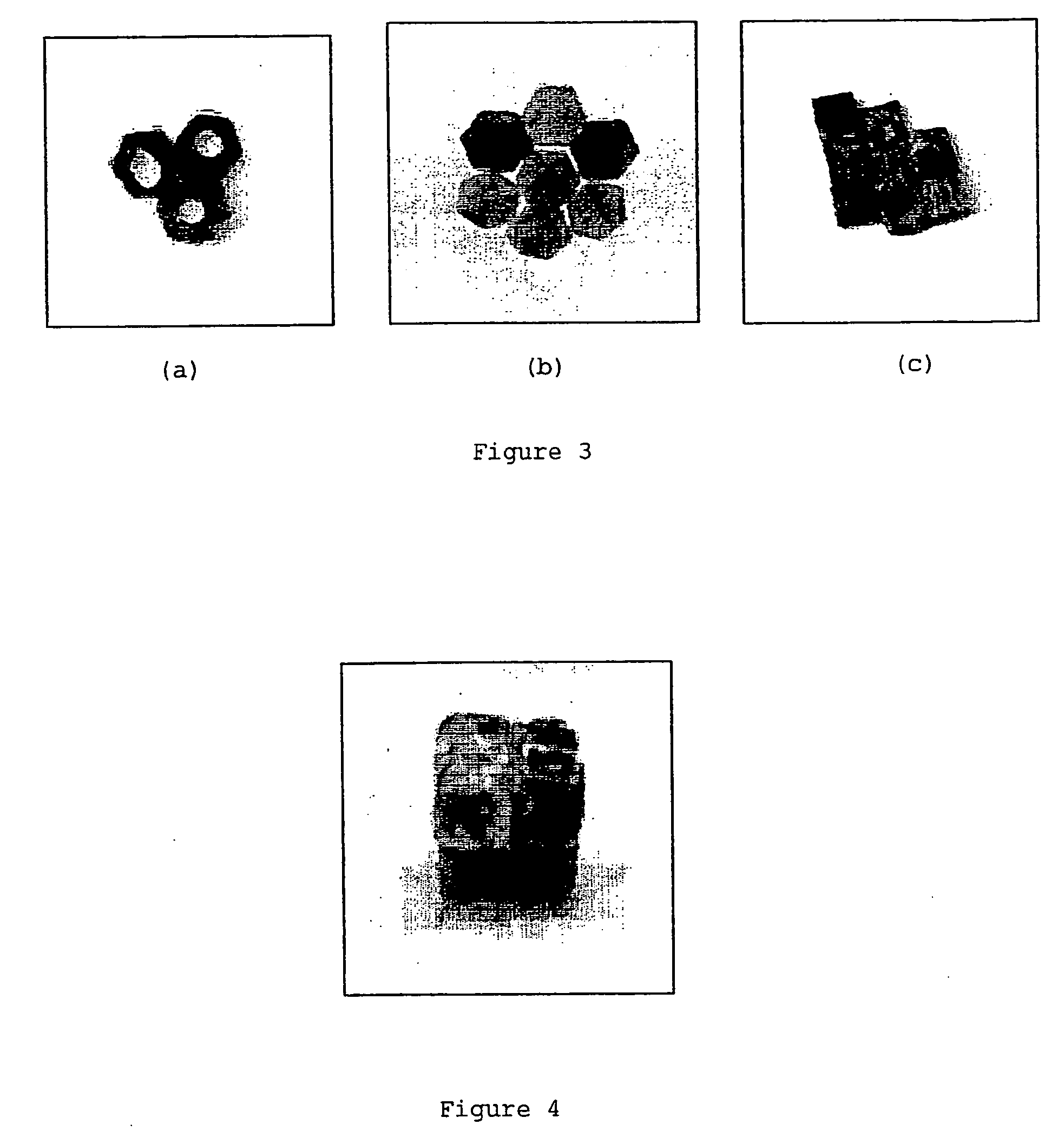
[0063] The individual composite building blocks (in the form of cubes or hexagons) were prepared by initially grinding polycaprolactone (PCL) with the porous powdered silicon material, obtained as described in WO01 / 95952, in various ratios by mass. The ratios prepared were as follows:

Mass of PCLMass of porousProductPowdersilicon powder1-D pentamer (FIG. 2b)0.3077 g0.0596 g2-D trimer (FIG. 3a)0.4181 g0.0827 g2-D hexamer (FIG. 3b)0.1652 g0.0338 g2-D octamer (FIG. 3c)0.6614 g0.1335 g3-D octamer (FIG. 4)0.6403 g0.1315 g

[0064] These composite powders were then poured into pre-formed PDMS molds with the desired 2-D shape (hexagonal or square). The molds were heated in an oven at 110° C. for −1 hr, and then cooled to room temperature. The solid composite blocks obtained could then be cut to the desired thickness between 0.8 mm to 4 mm.

Step 2

Preparation of Organized Assemblies:

[0065] The 2-D octamer illustrated in FIG. 3c was prepared as f...

example 2

Selective Enrichment of Selected Sites

[0067] Silicon powder material was spread on a rectangular glass slide. The glass slide was then placed over a hot plate and the temperature of the hot plate was adjusted to 200° C. Selected sites of composite building blocks (in the form of cubes or hexagons) prepared as described above were touched carefully with the hot silicon powder. The portion of the PCL polymer in contact with the hot silicon softened, leading to incorporation of the silicon material at those selected sites.

example 3

Calcification of BioSilicon Embedded in a Hollow PCL Cube

[0068] A composite structure composed of 11.4% mesoporous Si (w / w) was prepared by a method analogous to Example 1 and exposed to a solution of SBF at 37° C. for 14 days. Scanning electron microscopy was then used to examine the interior of a one dimensional channel in the structure. The image (FIG. 5) clearly showed numerous calcified deposits, the composition of which was confirmed in the corresponding energy dispersive x-ray spectrum. This result is in stark contrast to a control sample composed solely of PCL, where an absence of calcified deposits was evident on the surface of the material.


PUM

PropertyMeasurementUnit
melting pointaaaaaaaaaa
mass ratioaaaaaaaaaa
widthaaaaaaaaaa

Abstract

A process for preparing an orthopaedic scaffold, or other solid body, said process comprising forming shaped blocks of a bioactive material comprising silicon, treating one or more selected surfaces of said blocks such that they will adhere to a similarly treated surface of a similar block, and self-assembly of a scaffold comprising two or more of said blocks under conditions in which the treated surfaces will bind together, and thereafter recovering the assembled structure. Products including orthopaedic scaffolds obtained using this process are also provided.

Description

[0001] The present invention relates to processes for making self-assembly orthopaedic scaffolds for tissue engineering, and to the orthopaedic scaffolds obtained thereby. BACKGROUND OF THE INVENTION [0002] Tissue engineering (TE) embodies a major new trend in medicine that is helping the body to heal itself. Engineering new bone is expected to be an important TE area over the next decade since bone & cartilage are simpler cellular systems and the body already has an in-built regeneration system (“remodelling”) for bone. [0003] The need for bone replacement can arise from trauma, infection, cancer or musculoskeletal disease. Every year, surgeons in the USA alone perform over 450,000 bone grafts. Both natural and synthetic materials are used in a variety of approaches. [0004] A bone autograft is a portion of bone taken from another area of the skeletal system of the patient. Autografting is considered the gold standard in efficacy for procedures that require supplemental bone, but au...

Claims


Application Information

Patent Timeline
Patent Type & Authority Applications(United States)
IPC IPC(8): A61L27/00A61F2/28A61L27/02A61L31/02
CPCA61L31/028A61L27/025
Inventor CANHAM, LEIGH TREVORCOFFER, JEFFERY LEEMUKHERJEE, PRIYABRATS
Owner CANHAM LEIGH TREVOR
Why Eureka
Try Eureka