Thin film device and its fabrication method
a thin film and fabrication method technology, applied in the direction of semiconductor devices, basic electric elements, electrical equipment, etc., can solve the problems of difficult epitaxial thin film formation, high cost of sapphire substrate and sic substrate, and difficult direct epitaxial growth of ionic bond thin film on sic substrate, etc., to achieve easy deposited, improve characteristics, and reduce costs
- Summary
- Abstract
- Description
- Claims
- Application Information
AI Technical Summary
Benefits of technology
Problems solved by technology
Method used
Image
Examples
embodiment 1
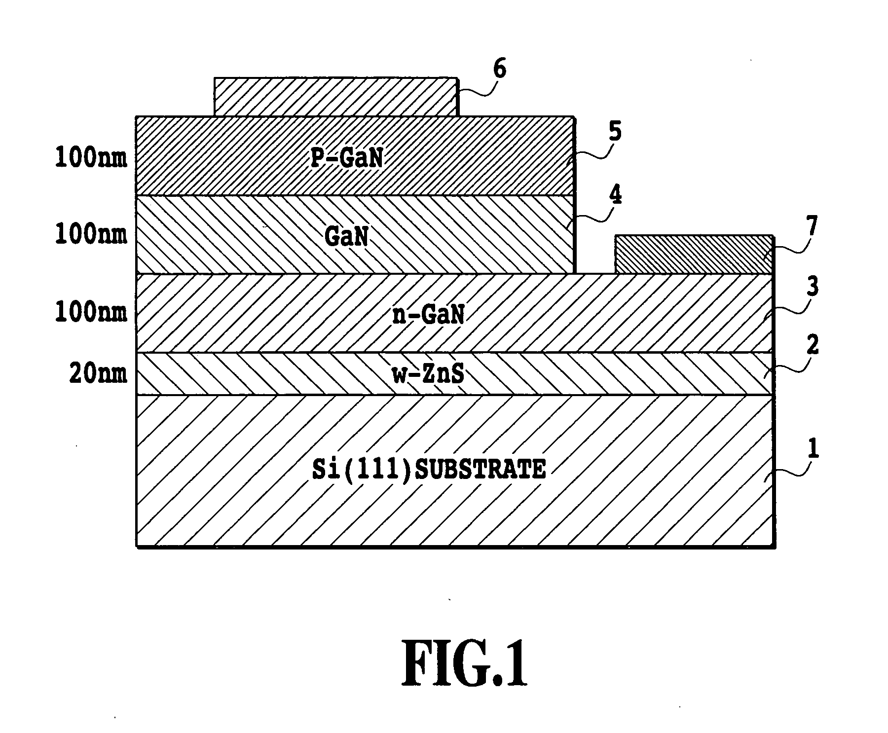
[0061]FIG. 1 shows a diagram illustrating a configuration of a GaN light emitting diode device formed according to the invention. In the drawing, 1 denotes a Si (111) single crystal substrate, 2 denotes a W-ZnS layer (20 nm; W indicates zinc sulfide of the wurtzite structure) deposited on the single crystal substrate 1, 3 denotes an n-GaN layer 3 (100 nm) deposited on the W-ZnS layer 2, 4 denotes a GaN layer (100 nm) deposited on the n-GaN layer, which functions as a luminescent layer, 5 denotes a p-GaN layer (100 nm) deposited on the GaN layer 4, 6 denotes an upper electrode formed on the p-GaN layer 5, and 7 denotes a lower electrode formed on the n-GaN layer3.
[0062] The Si (111) single crystal substrate was removed of a natural oxide film with Hydrogen Fluoride, cleaned with water, and then placed in a deposition chamber for vacuuming for about ten minutes. ZnS was deposited about 20 nm in thickness at a substrate temperature of 750° C. by Pulsed Laser Deposition (PLD). To form ...
embodiment 2
[0093]FIG. 10 shows a diagram illustrating a configuration of a thin film capacitor device fabricated according to the invention. In the drawing, 11 denotes an n-type Si (111) substrate, 12 denotes an Al doped W-ZnS layer (15 nm) deposited on the Si (111) substrate 11, 13 denotes an Al doped W-ZnO layer (400 nm) deposited on the Al doped W-ZnS layer 12, 14 denotes a SrTiO3 layer (190 nm) deposited on the Al doped W-ZnO layer 13, and 15 denotes an upper electrode (200 nm) formed on the SrTiO3 layer 14.
[0094] More specifically, the n-type Si (111) substrate 11 was used to deposit the wurtzite structural ZnS layer 12 of 15 nm in thickness, and the ZnO layer 13 was deposited 400 nm in thickness thereon. Subsequently, the SrTiO3 dielectric layer 14 was deposited, and the Pt upper electrode 15 was formed. A lower electrode is to be the Si substrate 11.
[0095] When ionic crystals such as SrTiO3 or the other perovskite oxides having a lattice constant close to that of platinum groups are e...
embodiment 3
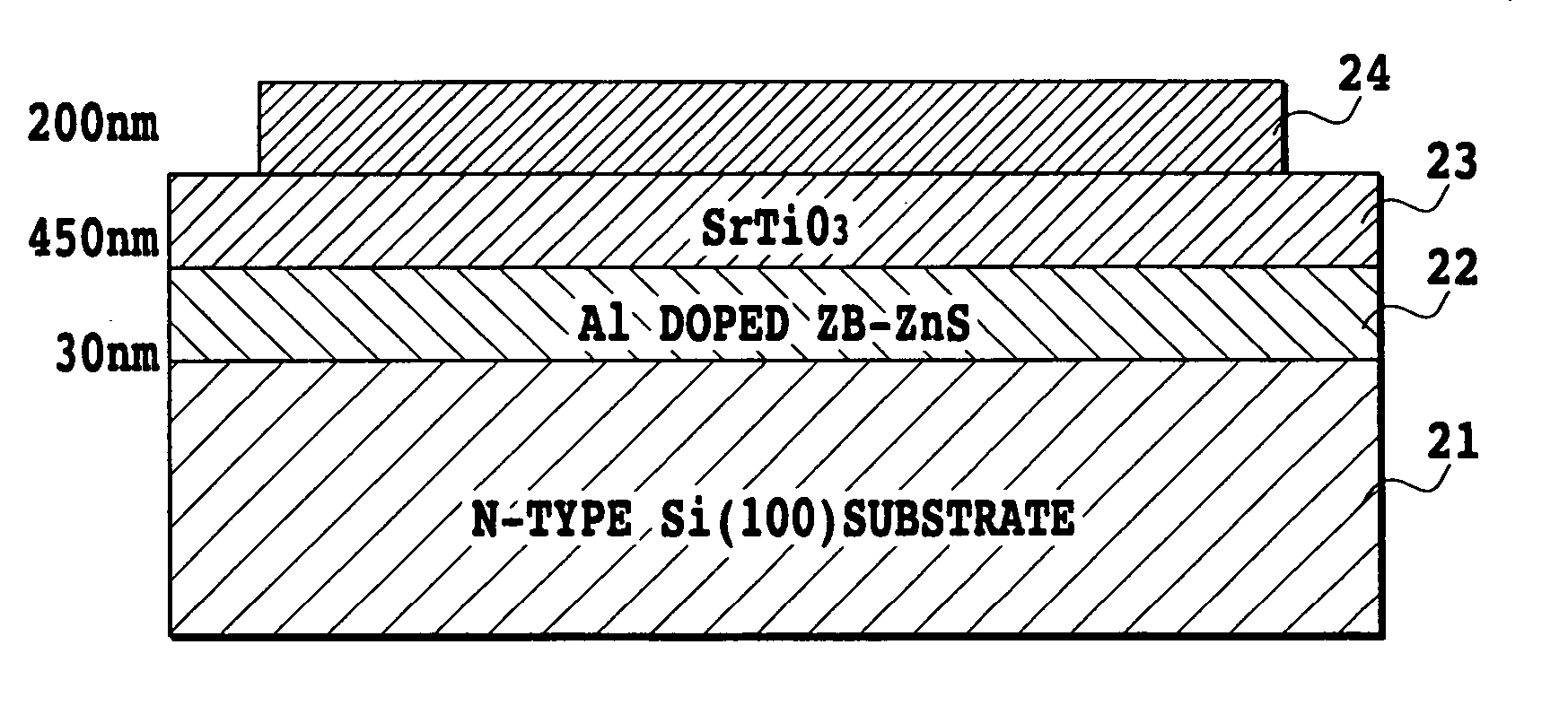
[0101]FIG. 14 shows a diagram illustrating a configuration of a thin film capacitor device fabricated according to the invention. In the drawing, 21 denotes an n-type Si (100) substrate, 22 denotes an Al doped ZB-ZnS layer (40 nm) deposited on the n-type Si (100) substrate 21, 23 denotes a SrTiO3 layer (450 nm) deposited on the Al doped ZB-ZnS layer 22, and 24 denotes an upper electrode (200 nm) formed on the SrTiO3 layer 23.
[0102] More specifically, the n-type Si (100) single crystal substrate 21 was used to deposit the zinc blend structural ZnS layer 22 of 30 nm in thickness, the SrTiO3 dielectric layer 23 was deposited thereon, and subsequently the Pt upper electrode 24 was formed. A lower electrode is to be the Si substrate 21.
[0103] The thin film capacitor device having such the structure is fabricated as follows. First, the n-type Si (100) single crystal substrate with low resistance was removed of a natural oxide film with Hydrogen Fluoride, cleaned with water, and then pla...
PUM
| Property | Measurement | Unit |
|---|---|---|
| lattice mismatch | aaaaa | aaaaa |
| temperature | aaaaa | aaaaa |
| temperature | aaaaa | aaaaa |
Abstract
Description
Claims
Application Information
 - R&D
- Intellectual Property
- Life Sciences
- Materials
- Tech Scout
- Unparalleled Data Quality
- Higher Quality Content
- 60% Fewer Hallucinations
Browse by: Latest US Patents, China's latest patents, Technical Efficacy Thesaurus, Application Domain, Technology Topic, Popular Technical Reports.
© 2025 PatSnap. All rights reserved.Legal|Privacy policy|Modern Slavery Act Transparency Statement|Sitemap|About US| Contact US: help@patsnap.com


