Method of increasing the shelf life of a photomask substrate

a technology of photomask and substrate, which is applied in the direction of auxillary/base layers of photosensitive materials, instruments, photosensitive materials, etc., can solve the problem of not providing as consistent a critical dimension

Inactive Publication Date: 2005-09-01
APPLIED MATERIALS INC
View PDF2 Cites 14 Cited by
  • Summary
  • Abstract
  • Description
  • Claims
  • Application Information

AI Technical Summary

Benefits of technology

[0014] By application of a pH adjusted protective topcoat, described above, over a CAR, it is possible to prepare an unexposed photoresist-coated substrate (wafer or reticle) months before its actual exposure, and to maintain the substrate in a patterning (imaging) tool for long time periods. This is in contrast with the use of an unprotected CAR which requires application of the photoresist to the substrate immediately prior to the pattern writing, and which does not provide as consistent a critical dimension during the entire photomask direct writing process.

Problems solved by technology

This is in contrast with the use of an unprotected CAR which requires application of the photoresist to the substrate immediately prior to the pattern writing, and which does not provide as consistent a critical dimension during the entire photomask direct writing process.

Method used


Image

  • Method of increasing the shelf life of a photomask substrate
  • Method of increasing the shelf life of a photomask substrate
  • Method of increasing the shelf life of a photomask substrate

Examples


example one

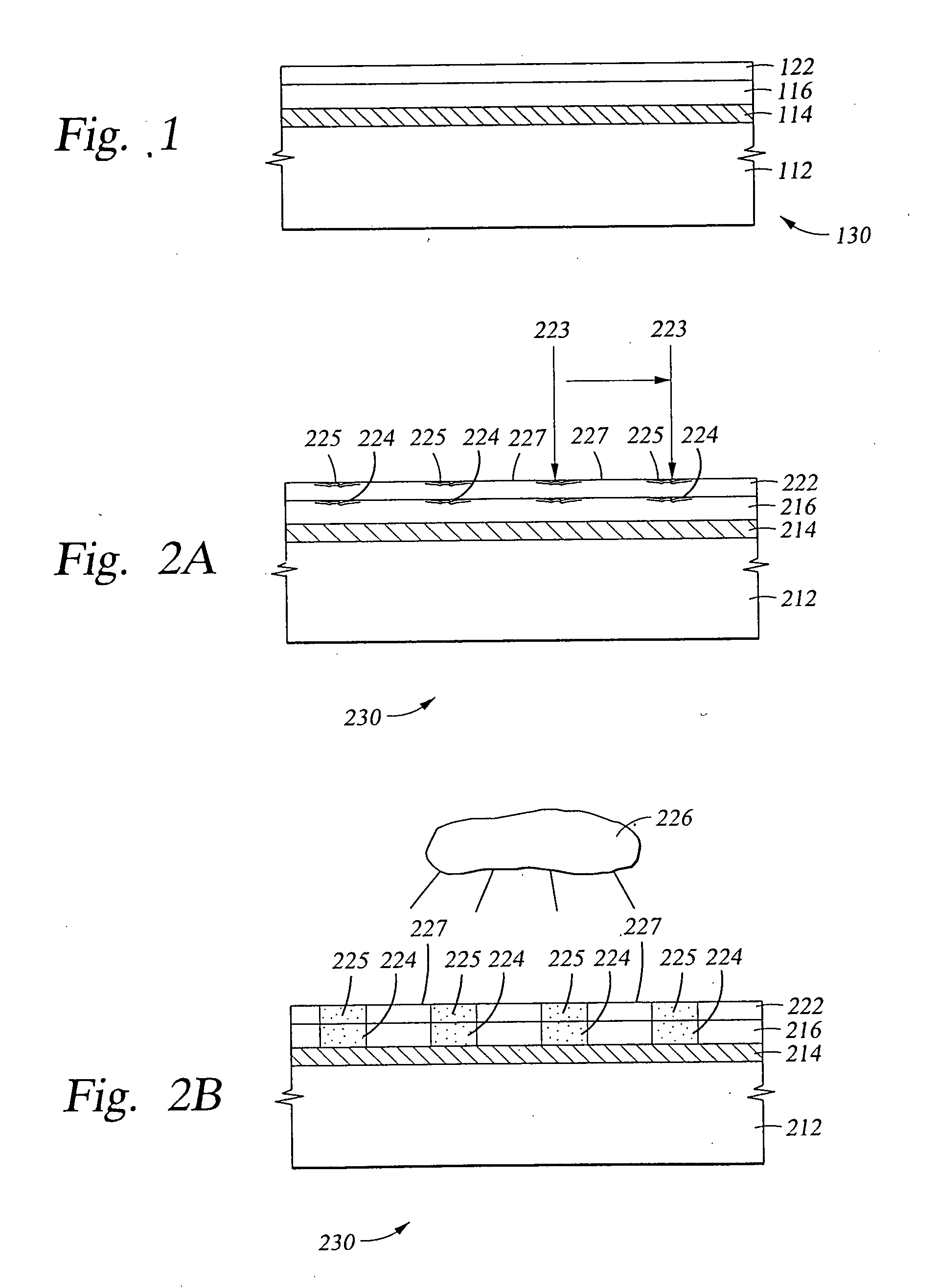
[0042] With reference to FIG. 2A, the substrate material 212, chrome-containing layer 214, and CAR layer 216 may be materials conventionally known in the art. For example, the CAR may be a positive tone photoresist such as APEX™, UVIIHS™, Rjv5™, and UV6™ manufactured by Shipley Co., Inc.; AZ DX1000P™, DX1200P™, and DX1300P™ manufactured by Clariant Corporation; ARCH8010™, and ARCH 8030™ manufactured by Arch Chemicals; ODUR-1010™ and ODtJR-1013™ manufactured by Tokyo Ohka Kogyo Co., Ltd.; and PRKI10A5™ manufactured by Sumitomo Chemicals, Inc. Examples of negative tone CARs are SAL-601™, and SAL-603 manufactured by Shipley Co., Inc.; EN-009PG™ manufactured by Tokyo Ohka Kogyo Co., Ltd., and NEB 22™ manufactured by Sumitomo Chemicals, Inc.

[0043] The topcoat material 222 applied over the CAR layer 216 may be a conventional material such as AQUATAR II™, AQUATAR III™, AQUATAR IV™, manufactured by Clariant Corporation, and NFC 540™ and NFC 620™ manufactured by JSR Chemical Co. of Japan, a...

example two

[0052] With reference to FIG. 2A again, the stability of the combination of the CAR 216 with the topcoat 222 is critically important in obtaining a uniform critical dimension for the direct write pattern across the entire surface of the substrate being patterned. In the present instance, an ALTA™ 257 nm direct write laser was used for writing of a pattern of lines 225 and spaces 227, where the lines 225 were 0.35μ in width and the spaces 227 between the lines were 0.35μ in width. After direct write imaging radiation 223 was applied to create an image 224 in CAR 216, the substrate 230 was baked as illustrated in FIG. 2B, to promote formation of a complete image 224 using application of a heat (which is illustrated by heat source 226, for example and not by way of limitation).

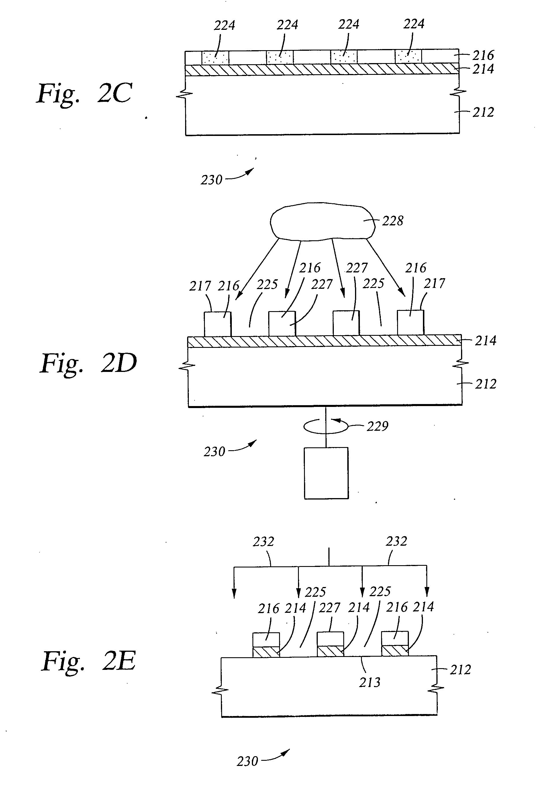
[0053] With reference to FIG. 2C, the neutral pH topcoat 222 has been removed to permit development of the underlying acidic imaged CAR 216. In some instances, where the topcoat 222 is removed by the developer f...


PUM

PropertyMeasurementUnit
wavelengthaaaaaaaaaa

Abstract

In photomask making, the environmental sensitivity of a chemically amplified photoresist is eliminated, or at least substantially reduced, by overcoating the photoresist with a thin coating (topcoat) of a protective but transmissive material. To provide improved stability during the long time period required for direct writing of a photomask pattern, typically in the range of about 20 hours, the protective topcoat material is pH adjusted to be as neutral in pH as possible, depending on other process variable requirements. For example, a pH adjusted to be in the range from about 5 to about 8 is particularly helpful. Not only is the stability of the chemically amplified photoresist better during direct writing when the protective topcoat is pH adjusted, but a photoresist-coated substrate with pH adjusted topcoat over its surface can be stored longer prior to imaging without adverse consequences.

Description

CROSS REFERENCE TO RELATED APPLICATIONS [0001] This application is a continuation-in-part of application Ser. No. 09 / 904,454, filed Jul. 12, 2001, presently pending, which is a continuation-in-part application of Ser. No. 09 / 293,713, filed Apr. 16, 1999, also presently pending.BACKGROUND OF THE INVENTION [0002] 1. Field of the Invention [0003] In general, the present invention relates to a method of fabrication of photomasks, sometimes referred to as reticles. In particular, the photomasks are fabricated using a direct write process which employs exposure of a chemically amplified photoresist to laser-produced Deep Ultra Violet (DUV) radiation or to electron beam radiation. [0004] 2. Brief Description of the Background Art [0005] Photoresist compositions are used in microlithographic processes for making miniaturized electronic components, such as in the fabrication of semiconductor device structures. The miniaturized electronic device structure patterns are typically created by tra...

Claims


Application Information

Patent Timeline
Patent Type & Authority Applications(United States)
IPC IPC(8): G03F7/039G03F1/08G03F7/004G03F7/09G03F7/11H01L21/027
CPCG03F7/0045G03F7/091G03F7/092Y10S430/146G03F7/11Y10S430/143G03F7/093G03F1/00G03F1/48G03F1/68
Inventor MONTGOMERY, MELVIN WARRENALBELO, JEFFREY A.HO TAN, ZOILO CHENG
Owner APPLIED MATERIALS INC
Why Eureka
Try Eureka