Magnetic recording medium and method for manufacturing the same

a technology of magnetic recording medium and manufacturing method, which is applied in the field of magnetic recording medium, can solve the problems of deterioration of magnetic characteristics, target cannot necessarily achieve its full ability, and guideline has not been elucidated, so as to reduce reliability, hinder granular structure formation, and deterioration of recording performances.

Active Publication Date: 2005-09-08
FUJI ELECTRIC DEVICE TECH CO
View PDF11 Cites 5 Cited by
  • Summary
  • Abstract
  • Description
  • Claims
  • Application Information

AI Technical Summary

Benefits of technology

[0033] Although a magnetic recording medium of the invention has been described with reference to FIG. 1, a magnetic recording medium of the invention shall not be limited to the above-described structure, but a seed layer, an intermediate layer and other layer may be appropriately added. For the purpose of controlling crystal alignment or other structure of the nonmagnetic underlayer or the granular magnetic layer, a seed layer may be provided between the nonmagnetic substrate and the nonmagnetic underlayer; and a nonmagnetic intermediate layer may be provided between the nonmagnetic underlayer and the granular magnetic layer. Addition of such layers also preserves the effects of the invention, or moreover, brings about superior performances.
[0034] The second aspect of the invention is a method for manufacturing a magnetic recording medium that is described above. The method of the invention comprises steps of sequentially laminating at least a nonmagnetic underlayer, a magnetic layer, a protective film, and a liquid lubrication layer on a nonmagnetic substrate, wherein the laminating steps are conducted without a step of preheating the nonmagnetic substrate.
[0035] The step of laminating the magnetic layer is conducted by means of a sputtering method using a target composed of a mixture including a ferromagnetic material containing at least cobalt and platinum, and an oxide of silicon. The composition of the target and the deposition conditions are suitably selected so that the deposited granular magnetic layer has the specified composition and structure.
[0036] For controlling the structure of the granular magnetic layer, the deposition of the layer is preferably conducted by means of an RF sputtering method under a pressure in the range of 5 mTorr to 30 mTorr. If the pressure of the deposition atmosphere is lower than 5 mTorr, formation of the granular structure is hindered because of deterioration of crystal alignment due to an initial growth layer and insufficient separation of the crystal grains, causing deterioration of a variety of characteristics. On the other hand, if the pressure is higher than 30 mTorr, lattice defects increases and crystal alignment is disturbed, causing deterioration of recording performances, and besides, brings upon lowering of reliability such as cobalt corrosion.
[0037] For depositing the granular magnetic layer, a target of a CoCrPt alloy containing an oxide including SiO2, for example, can be preferably used. A suitable proportion of the oxide contained in the target is appropriately selected depending on the composition of the target and the deposition conditions. A target used for depositing the magnetic layer, however, is not restricted so far as the target achieves the specified composition in the granular magnetic layer.
[0038] A method for manufacturing a magnetic recording medium according to the invention accomplishes a magnetic recording medium with high Hc and low media noise even if a step of substrate heating is omitted, which step has been essential in most of conventional methods. Thus, the method of the invention can reduce manufacturing costs by virtue of simplification of the manufacturing process. Since the substrate heating is unnecessary in the manufacturing method of the invention, an inexpensive plastic substrate made of polycarbonate, polyolefin, or other resins can be used as well as a conventional aluminum substrate and a glass substrate.

Problems solved by technology

The silicon atoms liberated by decomposition of SiO2 readily diffuse into the ferromagnetic alloy such as cobalt base alloy and are liable to cause degradation of magnetic characteristics.
As described above, even if a suitable target is selected, the target can not necessarily achieve its full ability when the target is deposited as a magnetic layer.
Nevertheless, such a guideline has not elucidated yet.

Method used


Image

  • Magnetic recording medium and method for manufacturing the same
  • Magnetic recording medium and method for manufacturing the same
  • Magnetic recording medium and method for manufacturing the same

Examples


example 1

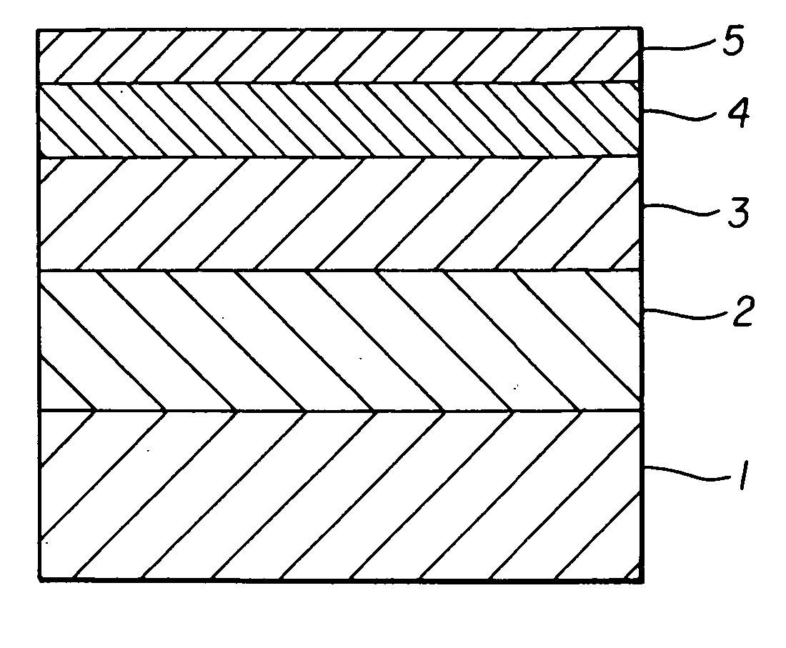
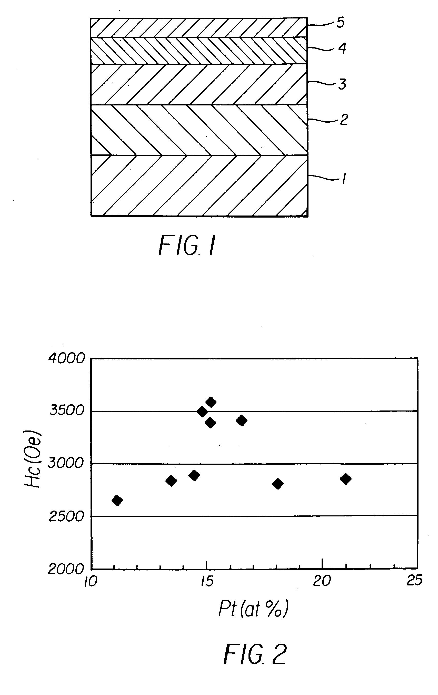
[0040] A disk shape substrate with 3.5 inch diameter made by injection molding polycarbonate resin was used for a nonmagnetic substrate. After cleaning, the substrate was introduced into a sputtering apparatus, and a ruthenium underlayer 30 nm thick was formed under an argon gas atmosphere of 30 mTorr. Subsequently, a granular magnetic layer 15 nm thick was formed by means of an RF sputtering method using a target of CO88-XCr12PtX containing 10 mol % of SiO2 under an argon gas atmosphere of 15 mTorr. The granular magnetic layers were deposited under the same conditions except that various targets were used containing platinum in proportion x from 10 to 25. After depositing a carbon protective layer 10 nm thick on each of the granular magnetic layers, the resulted article was taken out from the vacuum chamber. After that, liquid lubricant was applied to the thickness of 1.5 nm to produce a magnetic recording medium. Substrate heating prior to the deposition was not conducted.

[0041] ...

example 2

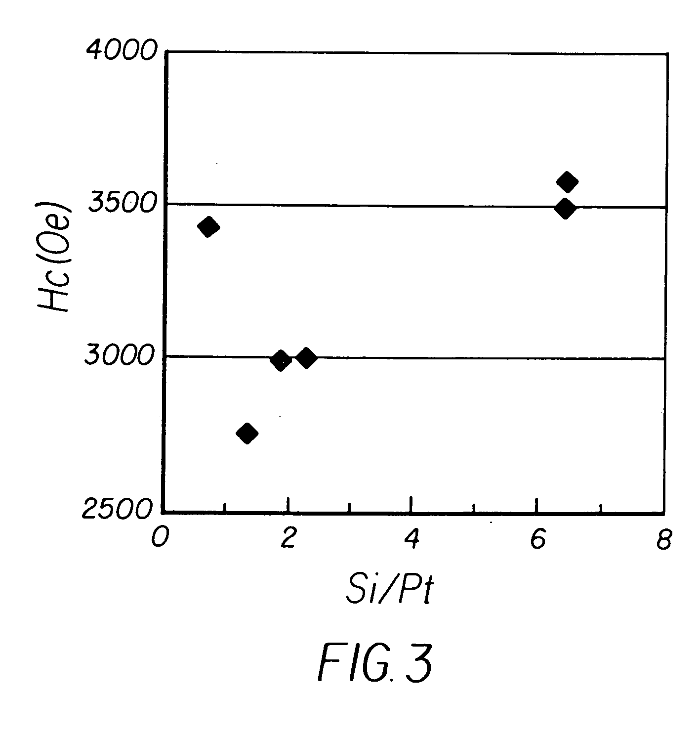
[0042] A plurality of magnetic recording medium was produced in the same manner as in Example 1 except that a granular magnetic layer was deposited using a target of CO76Cr12Pt12 containing 10 mol % of SiO2 under deposition conditions different from each other to control the platinum content being in the range of 15 at % to 17 at %. Composition of the grain boundary region in the granular magnetic layer of each of the obtained magnetic recording media was analyzed by means of EDS. FIG. 3 is a graph showing a relation between Si / Pt atomic ratio in the grain boundary region and the coercive force Hc of a magnetic recording medium. The graph of FIG. 3 shows a tendency of the He values in a low level when the Si / Pt atomic ratio is lower than 3, and high coercive force of about 3,500 [Oe] is achieved when the Si / Pt atomic ratio is larger than 6.

[0043] However, the coercive force Hc can be occasionally high even if the Si / Pt atomic ratio is low. Accordingly, the effect of the Si / Pt atomi...

example 3

[0045] Two recording media were produced in the same manner as in Example 1 except that each granular magnetic layer was formed by means of an RF sputtering method using a target of CO82Cr6Pt12 containing 6 mol % of SiO2 and 2 mol % of Cr2O3 under an argon gas atmosphere of 40 mTorr for the sample 3-1 or 15 mTorr for the sample 3-2.

[0046] Quantity of platinum in the ferromagnetic crystal grains in the granular magnetic layer of each of the obtained magnetic recording media was measured by means of EDS. The measured values of platinum content were 13 at % for the sample 3-1 and 16 at % for the sample 3-2. An Si / Pt atomic ratio in the grain boundary region of each sample was determined from composition analysis for the grain boundary region by means of EDS. Signal to noise ratio (SNR) was also measured for each sample at writing and reading density of 300 kFCI. The SNR was measured using a spinning stand tester. Writing and reading for the magnetic recording medium was done using the...


PUM

PropertyMeasurementUnit
pressureaaaaaaaaaa
diameteraaaaaaaaaa
thicknessaaaaaaaaaa

Abstract

A magnetic recording medium, and method of manufacturing the same, is provided with excellent recording performance by employing a granular magnetic layer having a specified composition. A magnetic recording medium according to the present invention comprises a nonmagnetic underlayer, a granular magnetic layer, a protective film, and a liquid lubrication layer sequentially laminated on a nonmagnetic substrate. The granular magnetic layer consists of ferromagnetic crystal grains containing cobalt and nonmagnetic grain boundary region surrounding the ferromagnetic crystal grains. The ferromagnetic crystal grains contain platinum in the range of 15 at % to 17 at %.

Description

BACKGROUND [0001] The present invention relates to a magnetic recording medium mounted on a variety of magnetic recording devices such as an external memory device of a computer. The invention also relates to a method for manufacturing such a medium. [0002] Remarkable technology development of magnetic recording devices in recent years is pushing for magnetic recording media with higher coercive force and lower noises. For addressing such demands, various proposals have been made concerning compositions and structure of a magnetic layer and materials of a nonmagnetic underlayer. [0003] Recently, a magnetic layer has been proposed having a structure in which ferromagnetic crystal grains are surrounded by nonmagnetic and nonmetallic substance, such as an oxide. Such a magnetic layer is generally called “a granular magnetic layer”. The granular magnetic layer is considered that interaction between the ferromagnetic crystal grains is decreased because the individual ferromagnetic crysta...

Claims


Application Information

Patent Timeline
Patent Type & Authority Applications(United States)
IPC IPC(8): C23C14/34C23C14/14G11B5/64G11B5/65G11B5/712G11B5/73G11B5/738G11B5/851H01F10/16H01F10/28
CPCG11B5/656G11B5/712Y10T428/12465Y10S428/90G11B5/851
Inventor NAKAMURA, MIYABISHIMIZU, TAKAHIROUWAZUMI, HIROYUKITAKIZAWA, NAOKIOIKAWA, TADAAKI
Owner FUJI ELECTRIC DEVICE TECH CO
Why Eureka
Try Eureka