

Method of manufacturing a semiconductor device and manufacturing system thereof
a manufacturing system and semiconductor technology, applied in the direction of semiconductor devices, electrical devices, transistors, etc., can solve the problems of lowering complicated wiring, and lowering the degree of the general purpose of the liquid crystal panel, so as to promote the elimination of hydrogen and enhance the degree of crystal structure. , the effect of improving the degree of order
- Summary
- Abstract
- Description
- Claims
- Application Information
AI Technical Summary
Benefits of technology
Problems solved by technology
Method used
Image

Examples
first embodiment
[0229] A first embodiment relates to a structure in which a crystalline silicon film is formed on a glass substrate. First, a silicon oxide film is formed on a glass substrate as an under layer. The silicon oxide film functions to relieve the diffusion of impurities in the glass substrate and a stress produced between the glass substrate and a semiconductor film. The silicon oxide film may be formed at a thickness of about 3000 Å through the plasma CVD technique or the sputtering technique.
[0230] Then, an amorphous silicon film is formed on the silicon oxide film. The amorphous silicon film may be formed through the plasma CVD technique or the decompression thermal CVD technique. The thickness of the amorphous silicon film may be set to a required value, but is set to 500 Å in this embodiment.
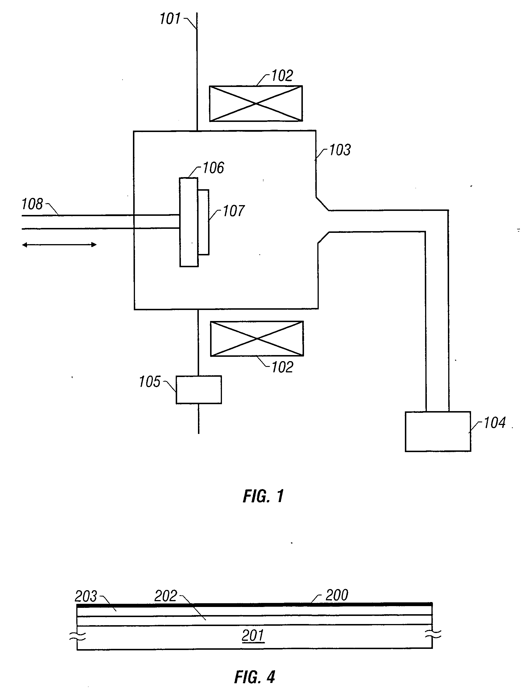
[0231] After the formation of the amorphous silicon film, a hydrogen plasma is produced under decompression through a technique using a magnetic field and a microwave, and the above-mentioned...
second embodiment
[0238] A second embodiment relates to a structure in which a crystalline silicon film is formed on a glass substrate, using the catalysis of a metal element. First, a silicon oxide film is formed on a glass substrate as an under layer. The silicon oxide film functions to relieve the diffusion of impurities in the glass substrate and a stress produced between the glass substrate and a semiconductor film. The silicon oxide film may be formed at a thickness of about 3000 Å through the plasma CVD technique or the sputtering technique.
[0239] Then, an amorphous silicon film is formed on the silicon oxide film. The amorphous silicon film may be formed through the plasma CVD technique or the decompression thermal CVD technique. The thickness of the amorphous silicon film may be set to a required value, but is set to 500 Å in this embodiment.
[0240] After the formation of the amorphous silicon film, metal elements that promote the crystallization of silicon is held in contact with the surfa...
third embodiment
[0250] A third embodiment relates to a structure in which the order of a process of introducing the metal elements that promote the crystallization of silicon and a process of the plasma processing are reversed in the processes described in the second embodiment. In other words, a plasma processing is conducted after the formation of the amorphous silicon film, and thereafter a plasma processing is conducted on the silicon film which has been plasma processing. With those processes, the inside of a chamber for conducting the plasma processing can be prevented from being contaminated by the metal elements.
PUM
| Property | Measurement | Unit |
|---|---|---|
| temperature | aaaaa | aaaaa |
| temperature | aaaaa | aaaaa |
| temperature | aaaaa | aaaaa |
Abstract
Description
Claims
Application Information