Positive-working photoimageable bottom antireflective coating

a technology of anti-reflective coating and photoresist, which is applied in the direction of photosensitive materials, instruments, photomechanical equipment, etc., can solve the problems of damage to the substrate, and damage to the photoresist pattern

Inactive Publication Date: 2005-09-29
AZ ELECTRONICS MATERIALS USA CORP
View PDF38 Cites 112 Cited by
  • Summary
  • Abstract
  • Description
  • Claims
  • Application Information

AI Technical Summary

Problems solved by technology

Thus, treatment of an exposed positive-working photoresist with a developer causes removal of the exposed areas of the photoresist coating and the formation of a positive image in the coating, thereby uncovering a desired portion of the underlying substrate surface on which the photoresist composition was deposited.
Furthermore, at lower wavelengths the reflection from the substrate becomes increasingly detrimental to the lithographic performance of the photoresist.
In addition, photoresist patterns may be damaged or may not be transferred exactly to the substrate if the dry etch rate of the antireflective coating is similar to or less than the etch rate of the photoresist coated on top of the antireflective coating.
The etching conditions for removing the organic coatings can also damage the substrate.
Bilevel photoresists are known, as in U.S. Pat. No. 4,863,827, but require exposure of two different wavelengths for the top and bottom photoresists, which complicates the processing of the lithography.
However this film is completely crosslinked to make it insoluble in an alkaline aqueous developer solution.
The dissolution of the antireflective coating is controlled by bake conditions and thus the antireflective coating is very sensitive to the developer normality and developing time, and also gives poor resolution.
High normality developer and / or long develop times can cause excessive removal of the antireflective coating.

Method used


Image

  • Positive-working photoimageable bottom antireflective coating
  • Positive-working photoimageable bottom antireflective coating
  • Positive-working photoimageable bottom antireflective coating

Examples


synthesis example 1

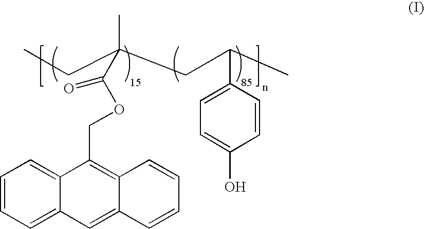
[0048] To a 250 ml 4 neck flask, equipped with a condenser, a thermometer, a nitrogen gas inlet and a mechanical stirrer, were added methacrylate ester of 9-anthracene methanol (AMMA) (4.2 g), 4-acetoxystyrene (13.8 g), azobisisobutylonitrile (AIBN) (0.8 g) and propyleneglycol monomethylether (PGME) (50 g). A solution was obtained and degassed for 15 minutes. Then the reaction mixture was heated to 70° C. and stirred at that temperature for 5 hours under flowing nitrogen. After the completion of the polymerization, the obtained solution was cooled down to the room temperature and tetramethylammonium hydroxide (26 wt % in water) solution (7 g) was added. The reaction temperature was raised to 40° C. and was kept for 3 hours before being raised to 60° C. After heating at 60° C. for 8 hours, the reaction mixture was cooled down to room temperature and was acidified to pH 6 using acetic acid. The resultant polymer was precipitated into 600 ml of methanol and the obtained solid was filte...

synthesis examples 2-5

[0049] Polymers with structures (II) to (V) were synthesized in the similar procedure as Synthesis Example 1 except using the different types and amount of monomers in accordance with the monomer ratio given in the structures.

example 1

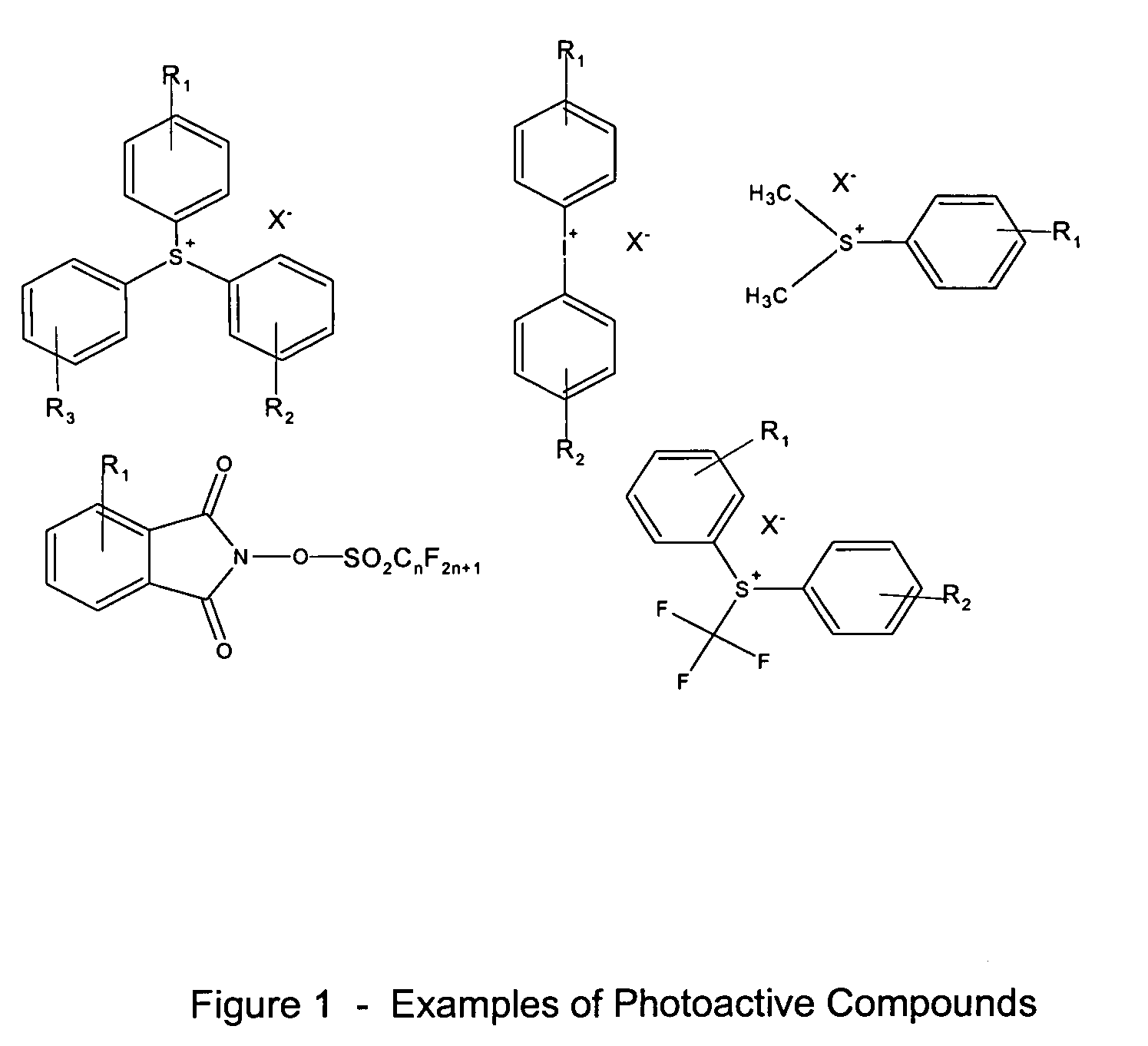
[0050] A copolymer represented by structure (I) from Synthesis Example 1 (2.5 g), tris(4-vinyloxy butyl) trimellitate (0.25 g, Vectomer®5015, available from Aldrich Co.), and triphenylsulfonium nonaflate (0.05 g) were dissolved in 68 g propyleneglycol monomethylether acetate (PGMEA) and 29 g of propyleneglycol monomethylether (PGME) to form an antireflective coating composition. The solution was filtered through a 0.1 μm filter.


PUM

PropertyMeasurementUnit
pKaaaaaaaaaaa
temperaturesaaaaaaaaaa
wavelengthaaaaaaaaaa

Abstract

The present invention relates to a positive bottom photoimageable antireflective coating composition which is capable of being developed in an aqueous alkaline developer, wherein the antireflective coating composition comprises a polymer comprising at least one recurring unit with a chromophore group and one recurring unit with a hydroxyl and/or a carboxyl group, a vinyl ether terminated crosslinking agent, and optionally, a photoacid generator and/or an acid and/or a thermal acid generator. The invention further relates to a process for using such a composition.

Description

FIELD OF INVENTION [0001] The present invention relates to novel positive-working, photoimageable, and aqueous developable antireflective coating compositions and their use in image processing by forming a thin layer of the novel antireflective coating composition between a reflective substrate and a photoresist coating. Such compositions are particularly useful in the fabrication of semiconductor devices by photolithographic techniques, especially those requiring exposure with deep ultraviolet radiation. These coatings are particularly compatible for use with an edge bead remover. BACKGROUND [0002] Photoresist compositions are used in microlithography processes for making miniaturized electronic components such as in the fabrication of computer chips and integrated circuits. Generally, in these processes, a thin coating of a film of a photoresist composition is first applied to a substrate material, such as silicon wafers used for making integrated circuits. The coated substrate is...

Claims


Application Information

Patent Timeline
Patent Type & Authority Applications(United States)
IPC IPC(8): G03F7/039G03F7/09
CPCG03F7/0392Y10S438/952Y10S430/115G03F7/091G03F7/039G03F7/09
Inventor SUI, YUWU, HENGPENGKANG, WENBINGNEISSER, MARK O.KATAYAMA, TOMOHIDEDING-LEE, SHUJI S.HISHIDA, ARITAKAOBERLANDER, JOSEPH E.TOUKHY, MEDHAT E.
Owner AZ ELECTRONICS MATERIALS USA CORP
Why Eureka
Try Eureka