

Diesel engine exhaust filters
a technology of diesel engine and filter body, applied in the field of filters, can solve the problems of large radial temperature gradient from the central axis of the filter to the outer skin of the filter, and achieve the effect of improving the resistance to thermal shock damag
- Summary
- Abstract
- Description
- Claims
- Application Information
AI Technical Summary
Benefits of technology
Problems solved by technology
Method used
Image

Examples
example 1
Wall Thickened Filter
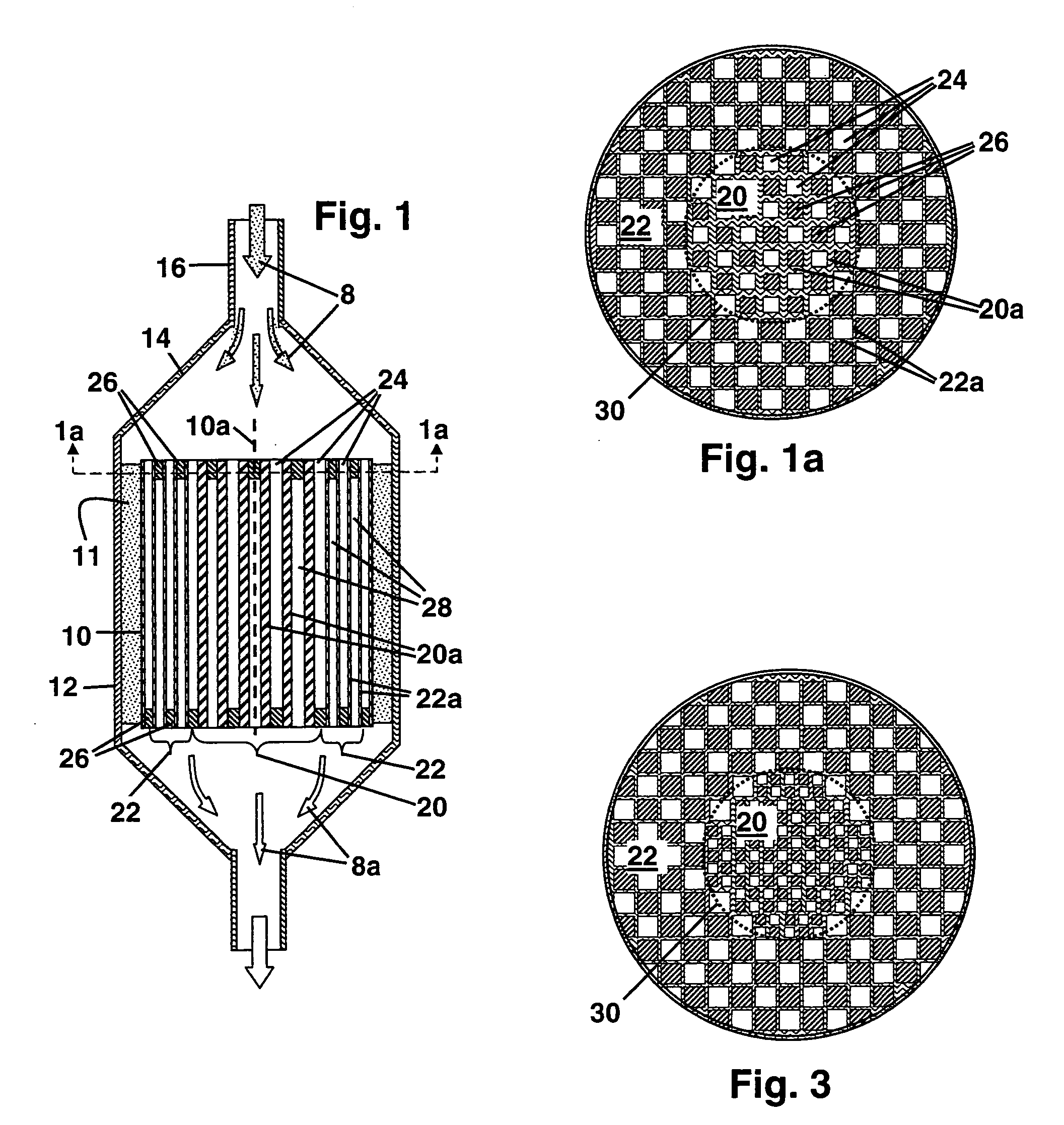
[0039] A conventional plasticized batch for ceramic honeycombs is first compounded of kaolin clay, talc, and alumina, these ingredients being provided in proportions suitable for developing a cordierite crystalline phase in the honeycomb following drying and firing. The batch further includes a methylcellulose temporary binder, a stearate lubricant, and water in a proportion sufficient to impart good plastic forming characteristics to the batch.
[0040] The batch thus provided is extruded through a steel honeycomb die of generally conventional design, wherein the plasticized mixture is conveyed into the die through an array of feedholes provided on the die entrance face. This batch is then fed within the die into an array of intersecting discharge slots opening onto the die discharge face for forming the batch into an intersecting honeycomb wall structure that is extruded from the discharge face as a honeycomb extrudate about 15 cm (6 inches) in diameter and of ...
example 2
Wall Flow Filter with Selective Wall Thickening
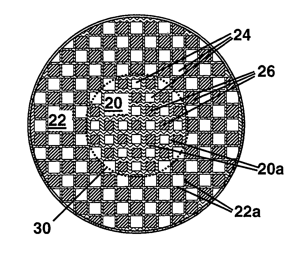
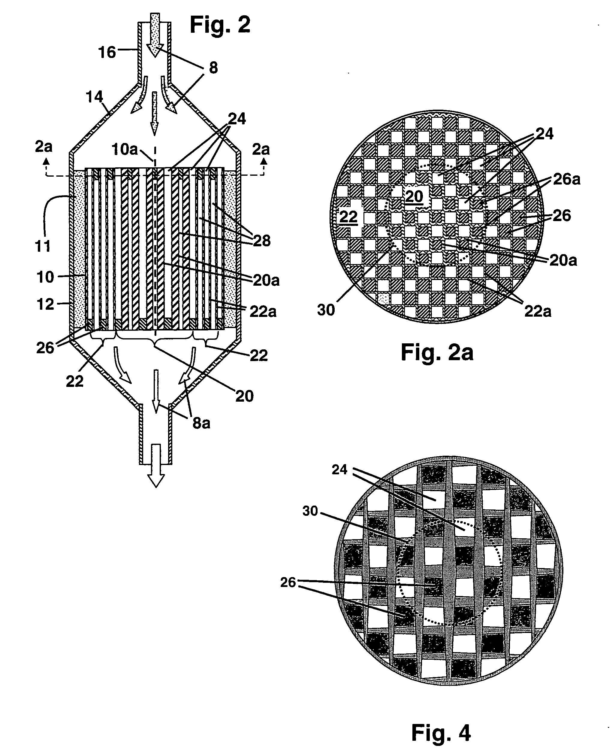
[0045] A plasticized batch for a ceramic honeycomb incorporating clay, talc alumina, a temporary binder, a lubricant, and water is compounded as described in Example 1 above. The batch thus provided is then extruded through a steel honeycomb die generally as described in Example 1 to produce a cylindrical honeycomb extrudate suitable for conversion to a wall flow filter. The slots in the discharge slot array for this honeycomb die again have a peripheral slot width of about 0.3 mm (0.012 inches), and are spaced to produce a square-channeled honeycomb cell density of 31 channels / cm2 (200 channels / in2) in the honeycomb extrudate after subsequent firing.
[0046] To extrude honeycombs with a modified wall structure in accordance with the invention, the discharge slot array of this extrusion die is again selectively modified prior to extrusion to increase the width of the discharge slots in a central section of the die discharge face. As in ...
example 3
Wall Flow Filter with Inserted Core Segment
[0051] A plasticized batch for a ceramic honeycomb incorporating clay, talc alumina, a temporary binder, a lubricant, and water is compounded as described in Example 1 above. The batch thus provided is then extruded through a steel honeycomb die generally as described in Example 1 to produce a cylindrical honeycomb extrudate about 15 cm (6 inches) in diameter that is suitable for conversion to a wall flow filter. The slots in the discharge slot array for this honeycomb die have a slot width of about 0.3 mm (0.012 inches), and are spaced to produce a square-channeled honeycomb cell density of 31 channels / cm2 (200 channels / in2) in the honeycomb extrudate after subsequent firing.
[0052] Sections cut from the honeycomb extrudate produced by this die are dried and fired to convert the sections into cordierite honeycombs of uniform channel wall thickness and channel cross-section. Next, cylindrical core segments about 5 cm (2 inches) in diameter...
PUM
| Property | Measurement | Unit |
|---|---|---|
| Thickness | aaaaa | aaaaa |
| Electrical resistance | aaaaa | aaaaa |
| Density | aaaaa | aaaaa |
Abstract
Description
Claims
Application Information