
Method and apparatus for intra-aortic substance delivery to a branch vessel

a branch vessel and substance technology, applied in the field of intra-aortic renal fluid delivery systems and methods, can solve the problems of patient arf, compromised safety, and inability to deliver the substance to the branch vessel,

Inactive Publication Date: 2005-11-03
ANGIODYNAMICS INC
View PDF99 Cites 165 Cited by
  • Summary
  • Abstract
  • Description
  • Claims
  • Application Information

AI Technical Summary

Benefits of technology

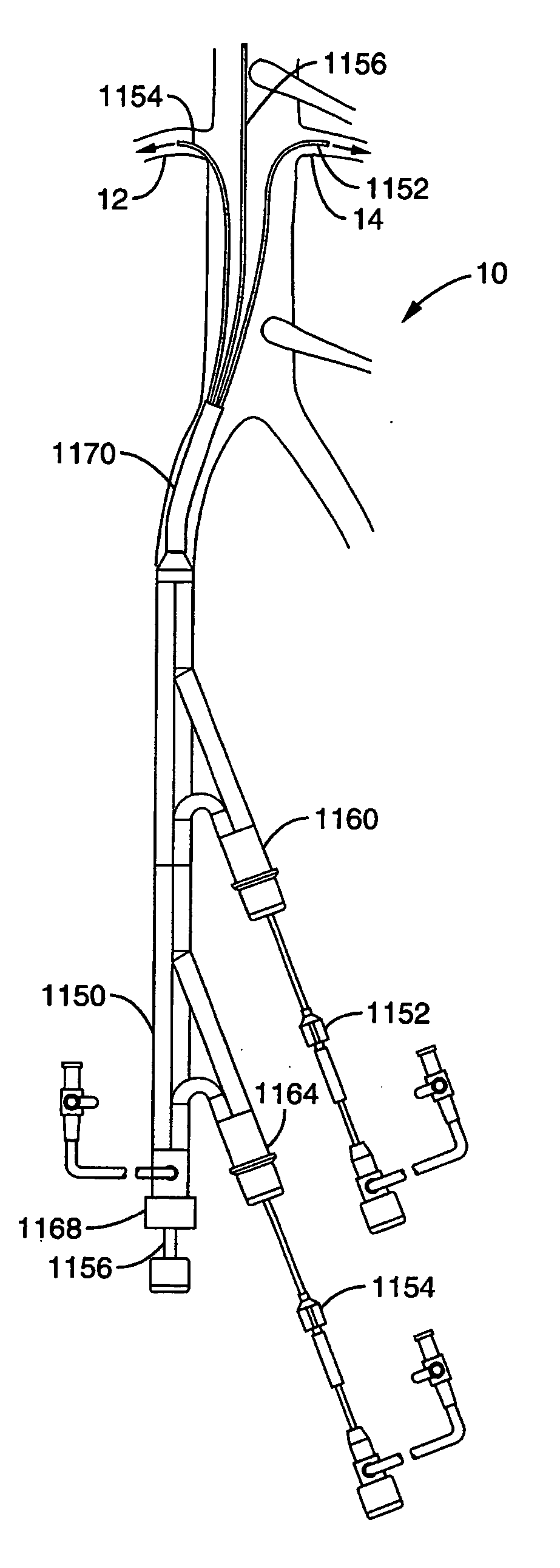
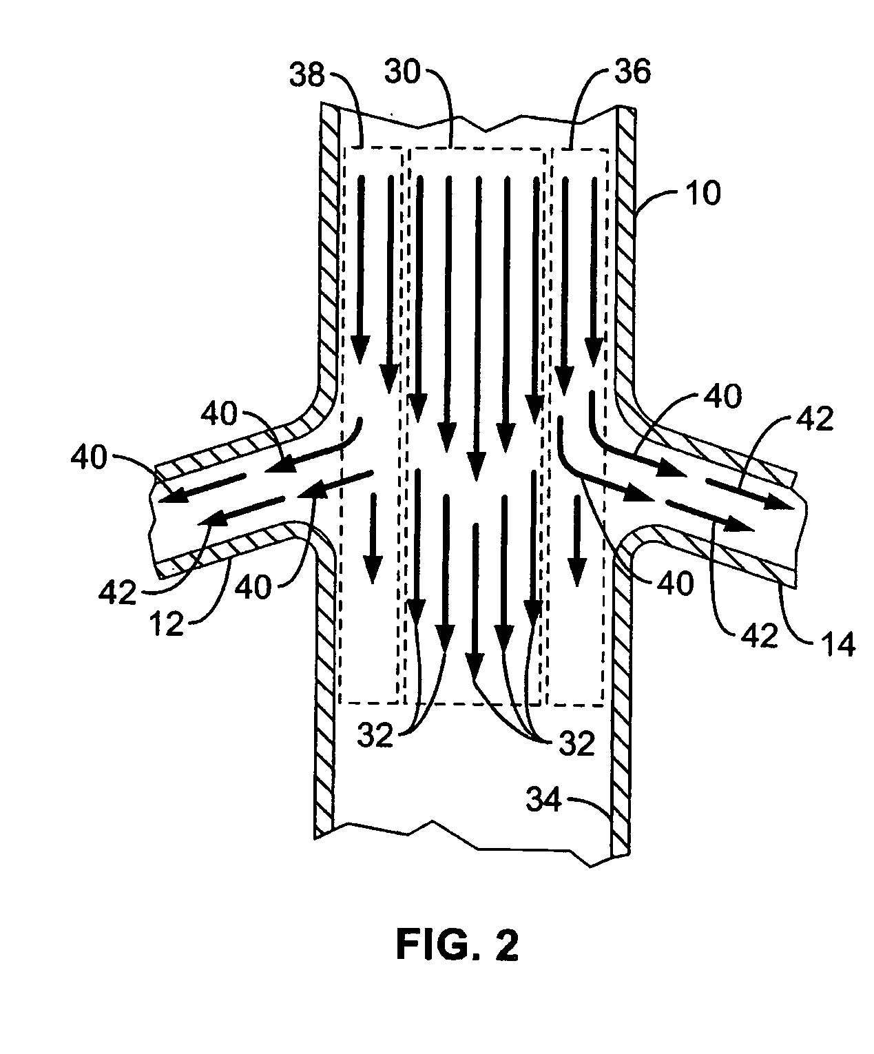
[0075] Another aspect of the invention is a method for providing local therapy to a renal system in a patient from a location within the abdominal aorta associated with first and second flow paths within an outer region of abdominal aortic blood flow generally along the abdominal aorta wall and into first and second renal arteries, respectively, via their corresponding first and second renal ostia along an abdominal aorta wall in the patient. This method includes positioning a local injection assembly at the location with first and second injection ports at first and second respective positions, respectively, corresponding with the first and second flow paths. Also included is fluidly coupling the local injection assembly to a source of fluid agent externally of the patient when the local injection assembly is positioned at the location, and injecting a volume of fluid agent from the source, through the first and second injection ports at the first and second positions, respectively, and bi-laterally into the first and second renal arteries, also respectively, via the respective corresponding first and second renal ostia without substantially altering abdominal aorta flow along the location.

Problems solved by technology

The agent's intended local effect is equally diluted and efficacy is compromised.
Thus systemic agent delivery requires higher dosing to achieve the required localized dose for efficacy, often resulting in compromised safety due to for example systemic reactions or side effects of the agent as it is delivered and processed elsewhere throughout the body other than at the intended target.
A traumatic event, such as hemorrhage, gastrointestinal fluid loss, or renal fluid loss without proper fluid replacement may cause the patient to go into ARF.
Patients may also become vulnerable to ARF after receiving anesthesia, surgery, or a-adrenergic agonists because of related systemic or renal vasoconstriction.
Reduced cardiac output caused by cardiogenic shock, congestive heart failure, pericardial tamponade or massive pulmonary embolism creates an excess of fluid in the body, which can exacerbate congestive heart failure.
For example, a reduction in blood flow and blood pressure in the kidneys due to reduced cardiac output can in turn result in the retention of excess fluid in the patient's body, leading, for example, to pulmonary and systemic edema.
However, many of these drugs, when administered in systemic doses, have undesirable side effects.
Additionally, many of these drugs would not be helpful in treating other causes of ARF.
Surgical device interventions, such as hemodialysis, however, generally have not been observed to be highly efficacious for long-term management of CHF.
Such interventions would also not be appropriate for many patients with strong hearts suffering from ARF.
The renal system in many patients may also suffer from a particular fragility, or otherwise general exposure, to potentially harmful effects of other medical device interventions.
For example, the kidneys as one of the body's main blood filtering tools may suffer damage from exposed to high density radiopaque contrast dye, such as during coronary, cardiac, or neuro angiography procedures.
One particularly harmful condition known as “radiocontrast nephropathy” or “RCN” is often observed during such procedures, wherein an acute impairment of renal function follows exposure to such radiographic contrast materials, typically resulting in a rise in serum creatinine levels of more than 25% above baseline, or an absolute rise of 0.5 mg / dl within 48 hours.
Therefore, in addition to CHF, renal damage associated with RCN is also a frequently observed cause of ARF.
These physiological parameters, as in the case of CHF, may also be significantly compromised during a surgical intervention such as an angioplasty, coronary artery bypass, valve repair or replacement, or other cardiac interventional procedure.
Notwithstanding the clear needs for and benefits that would be gained from such intra aortic drug delivery into the renal system, the ability to do so presents unique challenges as follows.
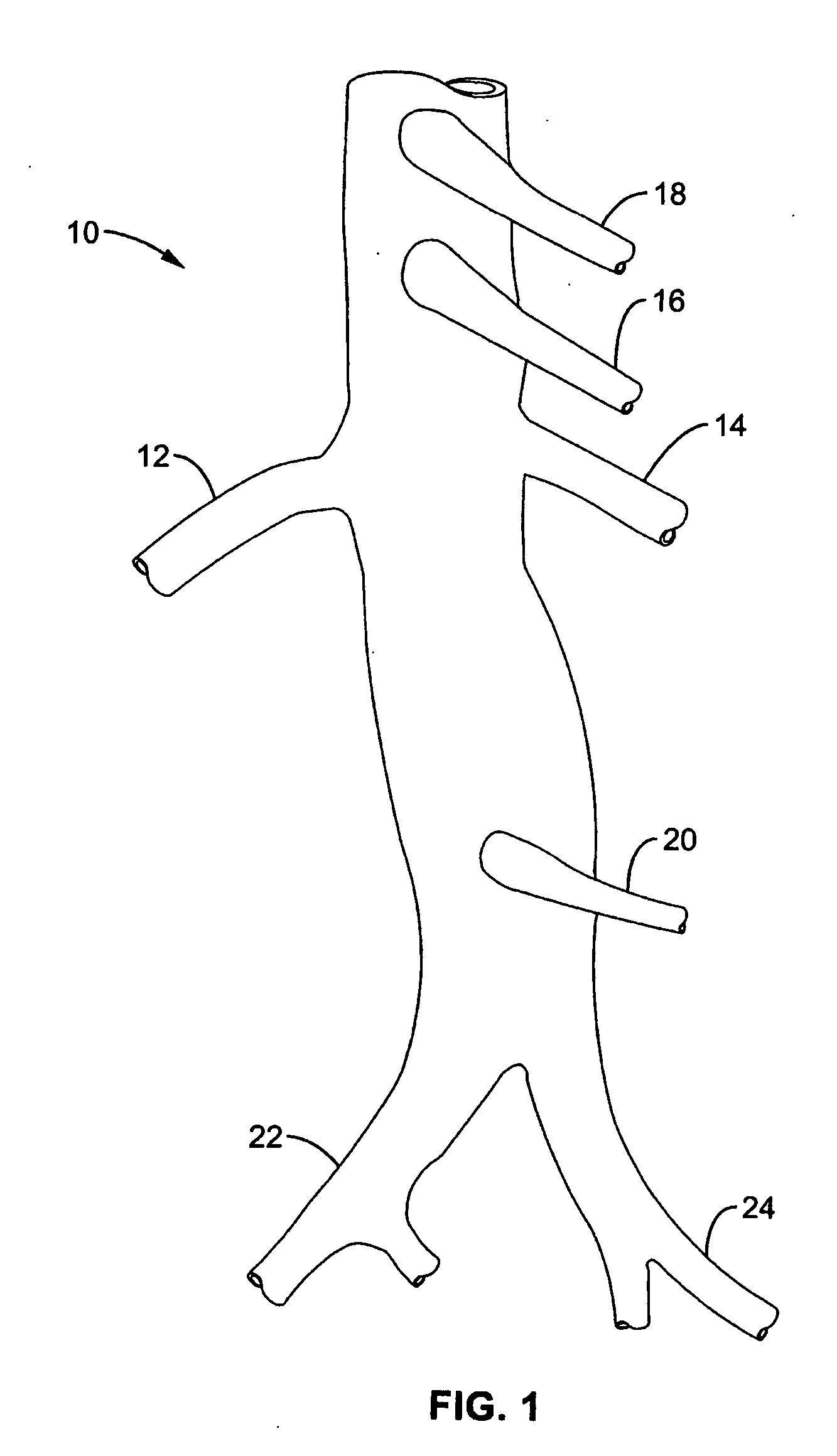
This presents a unique challenge to deliver drugs or other agents into the renal system on the whole, which requires both kidneys to be fed through these separate respective arteries via their uniquely positioned and substantially spaced apart ostia.
In another regard, mere delivery of an agent into the natural, physiologic blood flow path of the aorta upstream of the kidneys may provide some beneficial, localized renal delivery versus other systemic delivery methods, but various undesirable results still arise.
This reduces the amount of agent actually perfusing the renal arteries with reduced efficacy, and thus also produces unwanted loss of the agent into other organs and tissues in the systemic circulation (with highest concentrations directly flowing into downstream circulation).
However, such a technique may also provide less than completely desirable results.
For example, such seating of the delivery catheter distal tip within a renal artery may be difficult to achieve from within the large diameter / high flow aorta, and may produce harmful intimal injury within the artery.
This can become unnecessarily complicated and time consuming and further compound the risk of unwanted injury from the required catheter manipulation.
Moreover, multiple dye injections may be required in order to locate the renal ostia for such catheter positioning, increasing the risks associated with contrast agents on kidney function (e.g. RCN)—the very organ system to be protected by the agent delivery system in the first place.
Still further, the renal arteries themselves, possibly including their ostia, may have pre-existing conditions that either prevent the ability to provide the required catheter seating, or that increase the risks associated with such mechanical intrusion.
In particular, to do so concurrently with multiple delivery catheters for simultaneous infusion of multiple renal arteries would further require a guide sheath of such significant dimensions that the preferred Seldinger vascular access technique would likely not be available, instead requiring the less desirable “cut-down” technique.
However, the flow to lower extremities downstream from such balloon system can be severely occluded during portions of this counterpulsing cycle.
Moreover, such previously disclosed systems generally lack the ability to deliver drug or agent to the branch arteries while allowing continuous and substantial downstream perfusion sufficient to prevent unwanted ischemia.
Notwithstanding the interest and advances toward delivering agents for treatment or diagnosis of organs or tissues, the previously disclosed systems and methods summarized immediately above generally lack the ability to effectively deliver agents from within a main artery and locally into substantially only branch arteries extending therefrom while allowing the passage of substantial blood flow and / or other medical devices through the main artery past the branches.
This is in particular the case with previously disclosed renal treatment and diagnostic devices and methods, which do not adequately provide for local delivery of agents into the renal system from a location within the aorta while allowing substantial blood flow continuously downstream past the renal ostia and / or while allowing distal medical device assemblies to be passed retrogradedly across the renal ostia for upstream use.

Method used


Image

  • Method and apparatus for intra-aortic substance delivery to a branch vessel
  • Method and apparatus for intra-aortic substance delivery to a branch vessel
  • Method and apparatus for intra-aortic substance delivery to a branch vessel

Examples


Embodiment Construction

[0140] Referring more specifically to the drawings, for illustrative purposes the present invention is embodied in the apparatus generally shown in FIG. 3 through FIG. 59. It will be appreciated that the apparatus may vary as to configuration and as to details of the parts, and that the method may vary as to the specific steps and sequence, without departing from the basic concepts as disclosed herein.

[0141] The description herein provided relates to medical material delivery systems and methods in the context of their relationship in use within a patient's anatomy. Accordingly, for the purpose of providing a clear understanding, the term proximal should be understood to mean locations on a system or device relatively closer to the operator during use, and the term distal should be understood to mean locations relatively further away from the operator during use of a system or device. These present embodiments below therefore generally relate to local renal drug delivery generally ...


PUM


Abstract

A renal flow system injects a volume of fluid agent into a location within an abdominal aorta in a manner that flows bi-laterally into each of two renal arteries via their respectively spaced ostia along the abdominal aorta wall. A local injection assembly includes two injection members, each having an injection port that couples to a source of fluid agent externally of the patient. The injection ports may be positioned with an outer region of blood flow along the abdominal aorta wall perfusing the two renal arteries. A flow isolation assembly may isolate flow of the injected agent within the outer region and into the renals. The injection members are delivered to the location in a first radially collapsed condition, and bifurcate across the aorta to inject into the spaced renal ostia. A delivery catheter for upstream interventions is used as a chassis to deliver a bilateral local renal injection assembly to the location within the abdominal aorta.

Description

CROSS-REFERENCES TO RELATED APPLICATIONS [0001] This application is a continuation of PCT Patent Application No. PCT / US03 / 299995 (Attorney Docket No. 022352-001100PC), filed Sep. 22, 2003, which claims priority from U.S. Provisional Application Ser. Nos.: 60 / 412,343 (Attorney Docket No. 022352-000700US), filed on Sep. 20, 2002; 60 / 412,476 (Attorney Docket No. 022352-000800US), filed on Sep. 20, 2002; 60 / 479,329 (Attorney Docket No. 022352-000900US), filed on Jun. 17, 2003; and 60 / 502,389 (Attorney Docket No. 022352-00110US), filed on Sep. 13, 2003. The full disclosure of each of the foregoing applications is hereby incorporated by reference.BACKGROUND OF THE INVENTION [0002] 1. Field of the Invention [0003] This invention pertains generally to medical device systems and methods for intra aortic fluid delivery into regions of the body. More specifically, it is related to intra aortic renal fluid delivery systems and methods. [0004] 2. Description of Related Art [0005] Many different ...

Claims


Application Information

Patent Timeline
Patent Type & Authority Applications(United States)
IPC IPC(8): A61MA61M5/31A61M25/00A61M37/00
CPCA61M25/00A61M25/0041A61M25/0068A61M25/007A61M25/0071A61M2025/105A61M25/0075A61M25/0082A61M39/06A61M2025/0073A61M25/0074
Inventor ELKINS, JEFFREY M.VALENCIA, AURELIOPATEL, SAMIR R.ABOYTES, RICARDOGOODSON, HARRY B.BALL, CRAIG A.
Owner ANGIODYNAMICS INC
Learn More