Optical laminate

a technology of optical laminate and optical slit, which is applied in the field of optical laminate, can solve the problems of loss of raw materials, degrade production efficiency, and degrade production efficiency, and achieve the effect of high optical characteristics and high production efficiency

Active Publication Date: 2005-11-10
ZEON CORP
View PDF9 Cites 18 Cited by
  • Summary
  • Abstract
  • Description
  • Claims
  • Application Information

AI Technical Summary

Benefits of technology

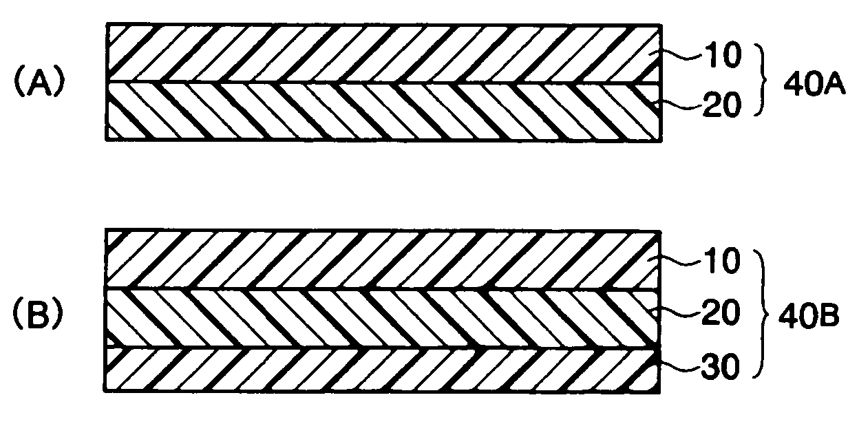
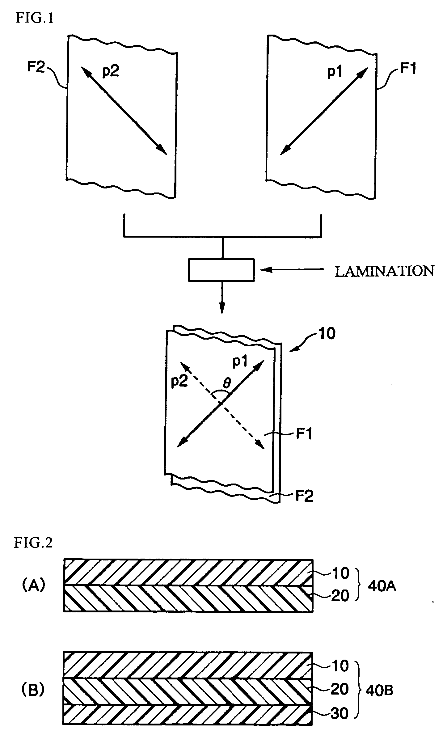
[0012] The inventors of the present invention conducted detail study to solve the above-described purposes, and found that a long optical laminate prepared by laminating two obliquely stretched long phase-difference films so that

Problems solved by technology

To manufacture the negative-retarder having the above-described structure, however, there is a problem of repeated troublesome works including sticking the cut-to-form chips together, which degrades the production efficiency.
To manufacture the above-described phase-difference plate (broad-band ¼ wavelength plate), however, there is

Method used


Image

  • Optical laminate
  • Optical laminate
  • Optical laminate

Examples


manufacturing example 1

[0136] Under a nitrogen atmosphere, 500 parts of dehydrated cyclohexane, 0.82 parts of 1-hexene, 0.15 parts of dibutylether, and 0.30 parts of tri-isobutylaluminum were poured in a reactor to mix them together at room temperature. While keeping the temperature of the mixture to 45° C., there were added continuously for two hours a norbornene-base monomer mixture consisting of 80 parts of tricyclo[4,3,0,12,5]deca-3,7-diene (dicyclopentadiene, (hereinafter referred to simply as DCP)), 70 parts of 7,8-benzotricyclo[4,4,0,12,5,17,10]deca-3-ene (methanotetrahydrofluorene, (hereinafter referred to simply as MTF)), and tetracyclo[4,4,0,12,5,17,10]dodeca-3-ene (tetracyclododecene, (hereinafter referred to simply as TCD)), and 40 parts of tungsten hexachloride (0.7% toluene solution), thus executed polymerization. To the polymerized solution, 1.06 parts of butylglycidylether and 0.52 parts of isopropyl alcohol were added to inactivate the polymerization catalyst to stop the polymerization re...

manufacturing example 2

[0140] The pellets obtained in Manufacturing Example 1 were dried in a hot-air drier with streaming hot air at 70° C. for 2 hours. The dried pellets were fed to a T-die film melt-extruder having a resin melting and kneading machine provided with a 65 mm size screw, thus formed an extrusion film having 100 μm of thickness under the condition of 240° C. of molten resin temperature and 500 mm of T-die width.

example 1

Manufacture of Optical Laminate

[0141] The film obtained in Manufacturing Example 2 was heated to 135° C., and was fed to the tenter-stretching machine shown in FIG. 9 to conduct continuous oblique-stretching thereto, thus obtained long stretched film having a stretch rate of 1.3 fold and an angle of delayed-phase axis to the width direction of the film of average 45 degrees. The tenter-stretching machine shown in FIG. 9 conducts oblique-stretching of film by moving left and right tenter clips (200) at an equal speed with each other, and by bending a film travel passage (220) while stretching a film (210) in the width direction thereof. The tenter-stretching machine provides a stretched film (230) having an angle θ (45 degrees in this case) between the delayed-phase axis and the film width direction.

[0142] The thickness, the content of volatile component, and the saturated water absorption of thus obtained stretched film were determined using the above-described respective methods ...


PUM

PropertyMeasurementUnit
Fractionaaaaaaaaaa
Angleaaaaaaaaaa
Angleaaaaaaaaaa

Abstract

Provided are: a long optical laminate prepared by laminating two obliquely stretched long phase-difference films so that the respective delayed-phase axes cross each other at a specified angle, while at least one of the two phase-difference films is a film containing residual volatile component by 1000 ppm or less; a long optical element prepared by laminating the optical laminate on one surface of polarization film; a long broad-band ¼ wavelength plate; an optical member prepared by laminating a circularly polarized light separating layer of cholesteric liquid crystal on one surface of the broad-band ¼ wavelength plate; a broad-band circular element using the broad-band ¼ wavelength plate; and an optical product having the broad-band circular polarization element. The invention provides long optical laminates having high optical characteristics stability, long broad-band ¼ wavelength plates, long optical elements, broad-band circular polarization elements, and various optical products having the broad-band circular polarization element.

Description

[0001] This application is a Continuation-In-Part of co-pending Application No. PCT / JP03 / 06695 filed on Mar. 28, 2003, the entire contents of which are hereby incorporated by reference and for which priority is claimed under 35 U.S.C. § 120.TECHNICAL FIELD [0002] The present invention relates to an optical laminate having a novel layer structure, an optical element having the optical laminate, a broad-band ¼ wavelength plate, a broad-band circular polarization element, an optical member, and an optical product having the broad-band circular polarization element. BACKGROUND ART [0003] A negative-retarder (a phase-difference element having a negative phase-difference in the vertical direction to the element plane) is known as a phase-difference plate which gives optical compensation to the characteristics of angle of visibility (angle-dependency of phase-difference) on a vertically aligned (VA) type liquid crystal display by inserting the phase-difference plate between a liquid crysta...

Claims


Application Information

Patent Timeline
IPC IPC(8): B29C55/04B32B7/03B32B37/12G02B5/30G02F1/1335
CPCB29C55/045B32B7/02B32B37/12B32B2038/0028B32B2307/40Y10T428/10G02B5/305G02B5/3083G02F1/133536Y10T428/1036B32B2307/42Y10T428/31504C09K2323/03C09K2323/00B32B7/03B32B27/08
Inventor MURAKAMI, TOSHIHIDEARAKAWA, KOHEI
Owner ZEON CORP
Why Eureka
Try Eureka