
Low Thermal Mass Fluorometer

a fluorometer and low thermal mass technology, applied in the field of low thermal mass fluorometers, can solve the problems of large and expensive system, limited budget, and limited space, and achieve the effects of improving thermal control, low cost, and adding spectral bandwidth

Inactive Publication Date: 2005-12-08
UNIV OF SOUTH FLORIDA
View PDF5 Cites 22 Cited by
  • Summary
  • Abstract
  • Description
  • Claims
  • Application Information

AI Technical Summary

Benefits of technology

[0011] The present invention provides core technologies necessary for a portable, low cost, thermal-regulating LED-based handheld fluorometer. The regulated fluorometer is based on a low thermal mass infrared heater, and an orthogonal geometry LED based filter fluorometer. Power is supplied through an external power supply and data is collected in real-time through standard serial interfaces of personal computers or personal digital assistants. Thermal regulation is automatically maintained using temperature sensor feedback control. Optical excitation relies on LED light source(s) and optical detection is through an adjustable integrating photodetector. Such a handheld system can allow applications requiring temperature sensitive photometric measurements for real time analyte detection to be performed in the field.
[0012] The fluorometer core technology as disclosed is expandable to a multi spectral fluorometer system for applications needing positive or negative controls and internal calibrants. Additional bandpass filters are interchangeable to accommodate added spectral bandwidth. Detector sensitivity is achieved by the use of a tunable integrating photodetector. Thermal control is improved by incorporating a pulse-width-modulated infrared heater and a thermopile based digital thermometer for accurate temperature regulation. This non-contact design allows the sample's fluorescence to be measured without interference from the thermal control system, and improves heat distribution within the sample. Additionally, the low thermal mass of the IR-controlled heating system allows for rapid and more efficient temperature cycling, compared to the higher thermal mass systems using metallic or ceramic heat-block systems.
[0013] In accordance with the present invention is a portable device, based on a 90° filter-based fluorometer and infrared thermal cycler. The device is an improvement in that it has a low thermal mass design, which allows for passive cooling and eliminates the need for a cooling fan. The system also yields a faster response time for isothermal heating, which is important for both reaction control, minimizing unwanted side reactions and for efficient power usage. The instrument employs a simplified mini radiant heater without the use of mirrors or lenses and has been designed to accept standard reaction tubes and eliminates the need for custom fluid vials and optical cells.

Problems solved by technology

Common bench top instrumentation platforms, including filter fluorometers, are large and expensive, and primarily target high throughput screening laboratory analysis.
Such systems offer little recourse for laboratories operating on limited budget, tight space restrictions, small sample throughput, or to technicians collecting samples in the field.

Method used


Image

  • Low Thermal Mass Fluorometer
  • Low Thermal Mass Fluorometer

Examples


Embodiment Construction

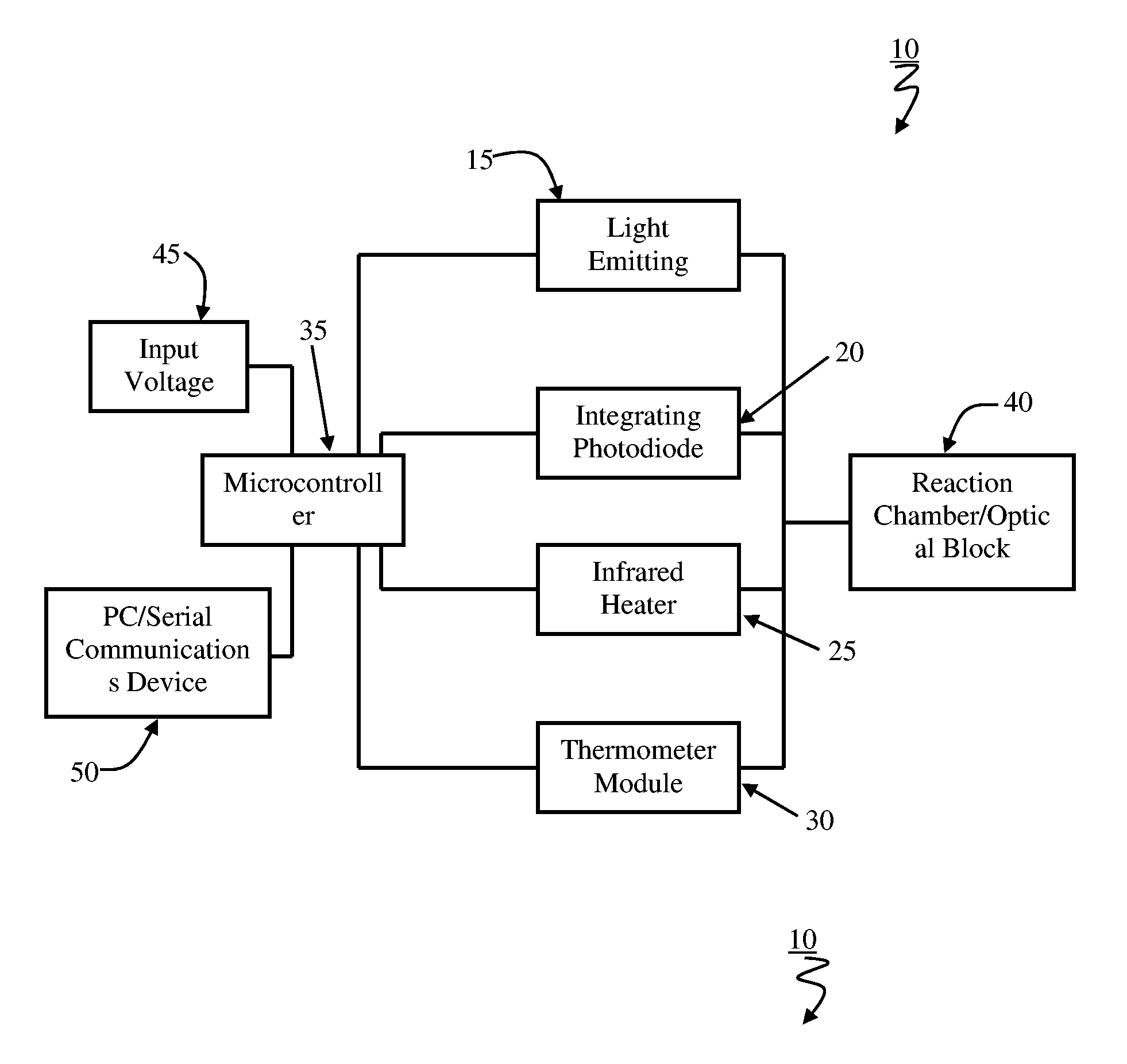
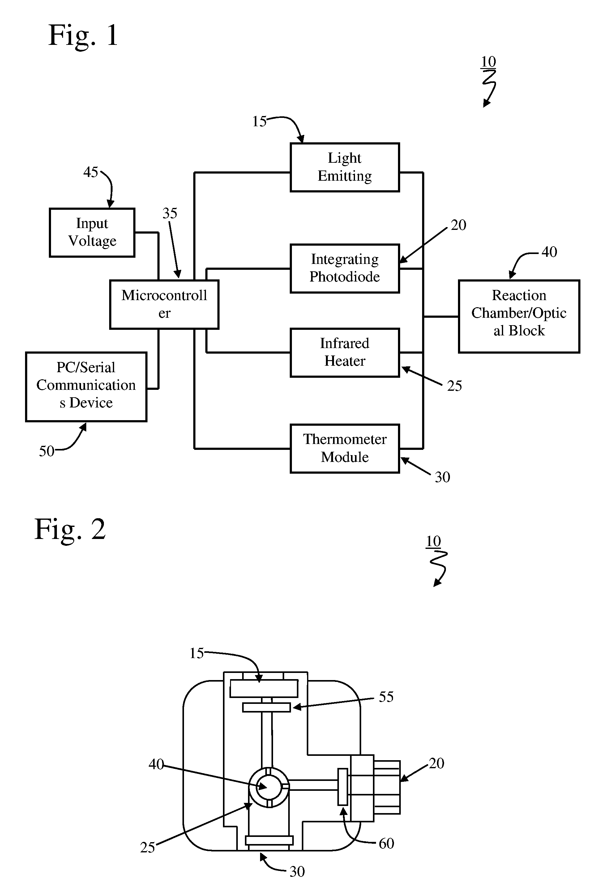
[0017] With reference to FIG. 1, in a particular embodiment the low thermal mass fluorometer 10 in accordance with the present invention incorporates a simple light emitting diode (LED) light source 15, and an integrating photodetector 20 for fluorometry. A MEMS-based infrared radiant heater 25 and an infrared thermometer module 30 make up the thermal regulation system. All of these components are controlled with custom software communicated through a microcontroller 35. In typical operation, the sample to be evaluated is placed in the reaction chamber 40. Power is supplied 45 either externally or through an integrated power supply and a serial communication interface 50 is used to provide a display for data output and a means to control the temperature cycling and optical parameters.

[0018]FIG. 2 illustrates the relative positioning of the elements of the low thermal mass fluorometer in accordance with the present invention. As shown the light emitting diode 15 and the photodetecto...


PUM


Abstract

The present invention provides core technologies necessary for a portable, low cost, thermal-regulating LED-based handheld fluorometer. The regulated fluorometer is based on a low thermal mass infrared heater, and an orthogonal geometry LED based filter fluorometer. Power is supplied through an external power supply and data is collected in real-time through standard serial interfaces of personal computers or personal digital assistants. Thermal regulation is automatically maintained using temperature sensor feedback control. Optical excitation relies on LED light source(s) and optical detection is through an adjustable integrating photodetector. Such a handheld system can allow applications requiring temperature sensitive photometric measurements for real time analyte detection to be performed in the field.

Description

CROSS REFERENCE TO RELATED APPLICATION [0001] This application claims benefit of pending provisional U.S. Ser. No. 60 / 521,602, filed Jun. 3, 2004.STATEMENT OF GOVERNMENT INTEREST [0002] This work has been supported by USA Space Missile Defense Command (SMDC) grant DASG-60-00-C-0089.BACKGROUND OF INVENTION [0003] The advent of molecular biological techniques has led to a dramatic increase in the speed, efficiency and species resolution obtained in microbiological studies from virtually every environment on earth. While this has revolutionized the way microbiology is performed, a requirement for access to laboratory facilities and infrastructure still exists, thereby introducing a spatial and temporal separation between sample collection and analysis. [0004] There has been an increasing need in the scientific and military communities to collect and analyze data in the field. In situ analysis holds many advantages over collecting samples, transporting them, and analyzing the samples in...

Claims


Application Information

Patent Timeline
IPC IPC(8): G01J1/58G01N21/03G01N21/64
CPCG01N21/0332G01N2201/0221G01N21/645
Inventor FARMER, ANDREWFRIES, DAVID P.FLANERY, BILL
Owner UNIV OF SOUTH FLORIDA
Learn More