Vaporizing temperature sensitive materials

Inactive Publication Date: 2005-12-22
GLOBAL OLED TECH
View PDF22 Cites 16 Cited by
  • Summary
  • Abstract
  • Description
  • Claims
  • Application Information

AI Technical Summary

Benefits of technology

[0018] It is an advantage of the present invention that it overcomes the need to have extremely uniform and constant material feed rate and substrate motion during deposition. In addition, the present invention overcomes heating and volume limitations of prior art devices in that only a small portion of material is heated to the desired rate-dependent vaporization temperature at a controlled rate. It is therefore a feature of the present invention to maintain a steady state time-varying vaporization process with a large charge of material, with pulsed heater temperature in synchronization with stepwise motion of the substrate. The present invention thus permits extended operation of the source with substantially reduced risk of degrading even very temperature sensitive materials. This feature additionally permits materials having different vaporization rates and degradation temperature thresholds to be co-sublimated in the same source.
[0019] It is another advantage of the present invention that it permits finer rate contr

Problems solved by technology

The organic materials used in the making of OLED devices are often subject to degradation when maintained at or near the desired rate-dependent vaporization temperature for extended periods of time.
Exposure of sensitive organic materials to higher temperatures can cause changes in the structure of the molecules and associated changes in material properties.
In this manner, the material is consumed before it has reached the temperature exposure threshold to cause significant degradation.
The limitations with this practice are that the available vaporization rate is very low due to the limitation on heater temperature, and the operation time of the source is very short due to the small quantity of material present in the source.
The low deposition rate and frequent source recharging place substantial limitations on the throughput of OLED manufacturing facilities.
A secondary consequence of heating the entire organic material charge to roughly the same temperature is that it is impractical to mix additional organic materials, such as dopants, with a host material unless the vaporization behavior and vapor pressure of the dopant is very close to that of the host material.
This is generally not the case and, as a result, prior art devices frequently require the use of separate sources to codeposit host and dopant materials.
While some of these disclosures discuss the use of powders, none teaches a method for delivering a powder or weakly cohesive solid at constant rate to the flash evaporation source and none discusses a suitable way to compensate for nonuniform delivery rate in a powder feed mechanism.
For deposition on stationary substrates, a limiting factor

Method used


Image

  • Vaporizing temperature sensitive materials
  • Vaporizing temperature sensitive materials
  • Vaporizing temperature sensitive materials

Examples


Embodiment Construction

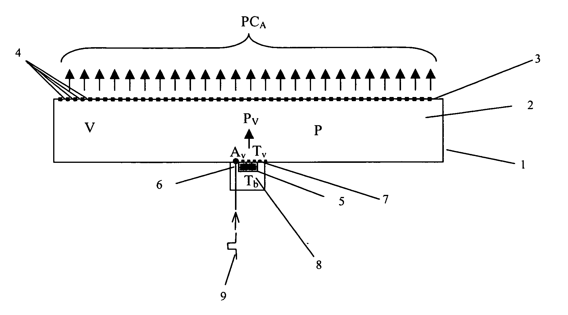
[0047] In order to illustrate the benefits of the present invention two models were constructed. The first model calculates the time-dependent pressure inside a vaporization manifold in response to heat pulses applied to an evaporant (i.e., material to be deposited by vaporization). The second model calculates the coating uniformity along the direction of motion of a substrate moved in stepwise fashion across a deposition zone containing a source that emits a vapor plume of specified shape.

[0048] The source geometry and model parameters are shown in FIG. 1. The deposition source 1 comprises a heated manifold 2 having an exit surface 3 with an aperture 4 or plurality of apertures 4 having total conductance CA. The evaporant 5 (i.e., material to be deposited, sublimate, material to be vaporized or sublimed) is located in a vaporization region 6 and is placed in contact with a heating element 7 on one surface, and is in contact with a region of lower temperature 8 on most of its remai...


PUM

PropertyMeasurementUnit
Temperatureaaaaaaaaaa
Thicknessaaaaaaaaaa
Electrical conductanceaaaaaaaaaa

Abstract

A method for vaporizing material onto a substrate surface to form a film includes providing a quantity of material into a vaporization apparatus, heating the material in the vaporization apparatus at a first temperature condition, and applying a heat pulse which acts on a portion of the material to cause such portion of the material to vaporize and be applied to the substrate surface.

Description

CROSS REFERENCE TO RELATED APPLICATIONS [0001] Reference is made to commonly assigned U.S. patent application Ser. No. 10 / 352,558 filed Jan. 28, 2003 by Jeremy M. Grace et al., entitled “Method of Designing a Thermal Physical Vapor Deposition System”, and commonly assigned U.S. patent application Ser. No. 10 / 784,585 filed Feb. 23, 2004 by Michael Long et al., entitled “Device and Method for Vaporizing Temperature Sensitive Materials”, the disclosures of which are herein incorporated by reference. FIELD OF THE INVENTION [0002] The present invention relates to the field of physical vapor deposition where a source material is heated to a temperature so as to cause vaporization and produce a vapor plume to form a thin film on a surface of a substrate. BACKGROUND OF THE INVENTION [0003] An OLED device includes a substrate, an anode, a hole-transporting layer made of an organic compound, an organic luminescent layer with suitable dopants, an organic electron-transporting layer, and a cath...

Claims


Application Information

Patent Timeline
IPC IPC(8): C23C14/12C23C14/24C23C14/26H01L51/00H01L51/40
CPCC23C14/12H01L51/0008C23C14/246C23C14/243H10K71/16
Inventor GRACE, JEREMY M.LONG, MICHAELKOPPE, BRUCE E.
Owner GLOBAL OLED TECH
Why Eureka
Try Eureka