Photoconductor, manufacturing method thereof, image forming process and image forming apparatus using photoconductor, and process cartridge

a manufacturing method and photoconductor technology, applied in the direction of electrographic process apparatus, instruments, corona discharge, etc., can solve the problems of higher wear rate of photoconductors, less durability of organic photoconductors, and high surface layer wear, so as to achieve high and stable scratch resistance, high and stable wear resistance, and advantageous electrical properties

Inactive Publication Date: 2005-12-22
RICOH KK
View PDF21 Cites 40 Cited by
  • Summary
  • Abstract
  • Description
  • Claims
  • Application Information

AI Technical Summary

Benefits of technology

[0013] The task of the present invention is to provide not only a photoconductor which has high and stable wear resistance, high and stable scratch resistance and advantageous electrical properties, and which can maintain an image having high quality for a long term; and a manufacturing method thereof, but also an image forming method, image forming apparatus and process cartridge using the above-noted phtoconductor having long life and high performance.

Problems solved by technology

However, organic photoconductors are typically less durable since the hardness of the surface layers is relatively low due to their inherent components of charge transport substances of lower molecular mass and inactive polymers; therefore, the surface layers tend to wear significantly due to mechanical stress caused by developing systems and cleaning systems etc. under repeated usages in electrophotographic processes.
Further, rubber hardness of cleaning blades has been raised and pressure onto photoconductors applied from the cleaning blades has been increased so as to improve cleaning ability in order to enhance image quality by using toner particles with smaller particle sizes, which inevitably leading to higher wear rate of photoconductors.
The wear of photoconductors certainly degrades sensitivity, electrical properties such as charging ability etc., which resulting in deteriorated images such as lower image density and background smear.
Further, flaws due to local wear often bring about streak on images due to insufficient cleaning.
Such wear and flaws typically dominate photoconductors in terms of lifetime to be exchanged, currently.
However, in the (1) incorporation of curable binders described above, residual voltage tends to increase owing to impurities such as polymerization initiators and / or unreacted residual groups due to insufficient compatibility with charge transport substances, thus image density tents to decrease.
In the method (2) using a charge transport polymer and the method (3) using an inorganic filler, while the wear resistance of the photoconductor can be improved to some extent, a photoconductor which can fully satisfy the durability required for the organic photoconductor is not yet obtained.
As such, based on these proposals (1), (2), and (3), the durability of organic photoconductors is not satisfactory on the whole, including electrical durability and mechanical durability.
However, there exist no more than simple descriptions that a charge transport substance may be contained in the protective layer and there exist no specific examples.
Further, when a charge transport substance having a low molecular mass is simply added to the surface layer, it may cause problems related with the compatibility to the cured body, thereby crystallization of charge transport substance having a lower molecular mass and clouding may occur, resulting in reduction in mechanical properties.
In addition, a photoconductor is produced by way of causing reaction of monomers in a condition that a polymer binder is incorporated; therefore, there will be some problems that the curing cannot sufficiently proceed, and surface nonuniformity is induced due to phase separation at curing caused by insufficient compatibility between the cured material and the binder resin, which resulting in inferior cleaning in image forming apparatuses.
However, non-reactive resins as the binder resin tend to yield surface irregularity and thus inferior cleaning, since the non-reactive resins are typically non-compatible with reaction products between the monomer and the charge transport substance, thus phase separation is likely to occur.
Further, the patent literature discloses monomers having two functionalities as specific examples, which cannot bring about sufficient crosslinking density and satisfactory wear resistance due to the lower functionalities.
Provided that reactive resins are employed as the binder resin, the bonding density and the crosslinking density are possibly not sufficiently high due to the lower functionalities of the monomer and the binder resin, thus electrical properties and wear resistance will not be satisfactory.
However, the photosensitive layer tends to cause higher internal stress and thus to yield higher surface roughness and cracks, since the bulky hole transport compound have two or more chain polymerizable functional groups.
However, it was also found that such a crosslinked resin layer has not a satisfactory durability during a long-term using and depending on the crosslinking condition, the surface properties of the crosslinked resin layer are largely changed and the surface unevenness of the crosslinked resin layer becomes easily large.
Accordingly, the cleaning failure of the photoconductor is easily caused and when the photoconductor is used in a long-term, the cleaning blade is locally broken and the cleaning failure is caused, so that an abnormal image in the form of a stripe is caused.

Method used


Image

  • Photoconductor, manufacturing method thereof, image forming process and image forming apparatus using photoconductor, and process cartridge
  • Photoconductor, manufacturing method thereof, image forming process and image forming apparatus using photoconductor, and process cartridge
  • Photoconductor, manufacturing method thereof, image forming process and image forming apparatus using photoconductor, and process cartridge

Examples


example 1

[0189] An undercoat layer was disposed on a support made of aluminum (having an outer diameter of 30 mm) by coating the support with the following coating liquid according to a dip coating so that the undercoat layer had a thickness of 3.5 μm after drying the coating.

[0190]

Composition of Coating LiquidAlkyd resin (manufactured and sold by Dainippon Ink &6partsChemicals Inc.; trade name: Beckozole 1307-60-EL)Melamine resin(manufactured and sold by Dainippon Ink &4partsChemicals Inc.; trade name: Super Beckamine G-821-60)Titanium oxide(manufactured and sold by Ishihara40partsSangyo Kaisha Ltd.; trade name: CR-EL)Methyl ethyl ketone50parts

[0191] A charge generating layer was disposed on the above-disposed undercoat layer by coating the undercoat layer with a coating liquid for disposing the charge generating layer, which comprised a bisazo pigment represented by the following formula according to a dip coating, and the resultant coating was dried by the heating so that the charge gene...

example 2

[0197] The photoconductor of Example 2 was produced in substantially the same manner as in Example 1, except that in the light energy irradiating vessel, air was purged with argon gas until an oxygen concentration was lowered to 0.05 vol % to 0.12 vol %.

example 3

[0198] The photoconductor of Example 3 was produced in substantially the same manner as in Example 1, except that as the radical polymerizable compound having a charge transport structure, Compound No. 182 was used. The thickness of the crosslinked layer of the obtained photoconductor was measured and found to be 4.4 μm.


PUM


Abstract

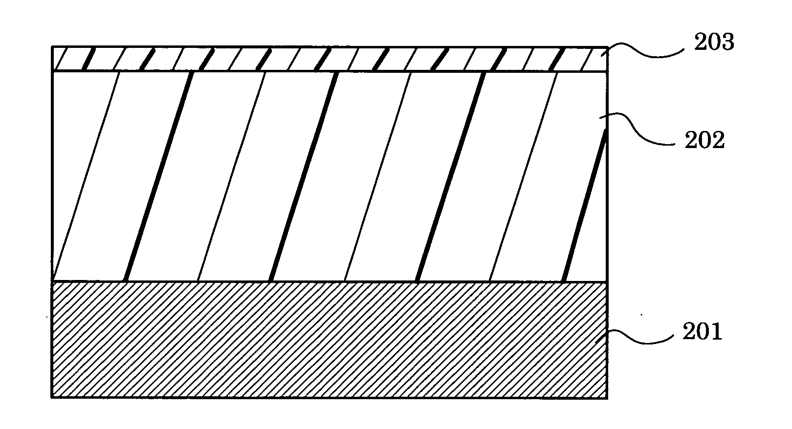
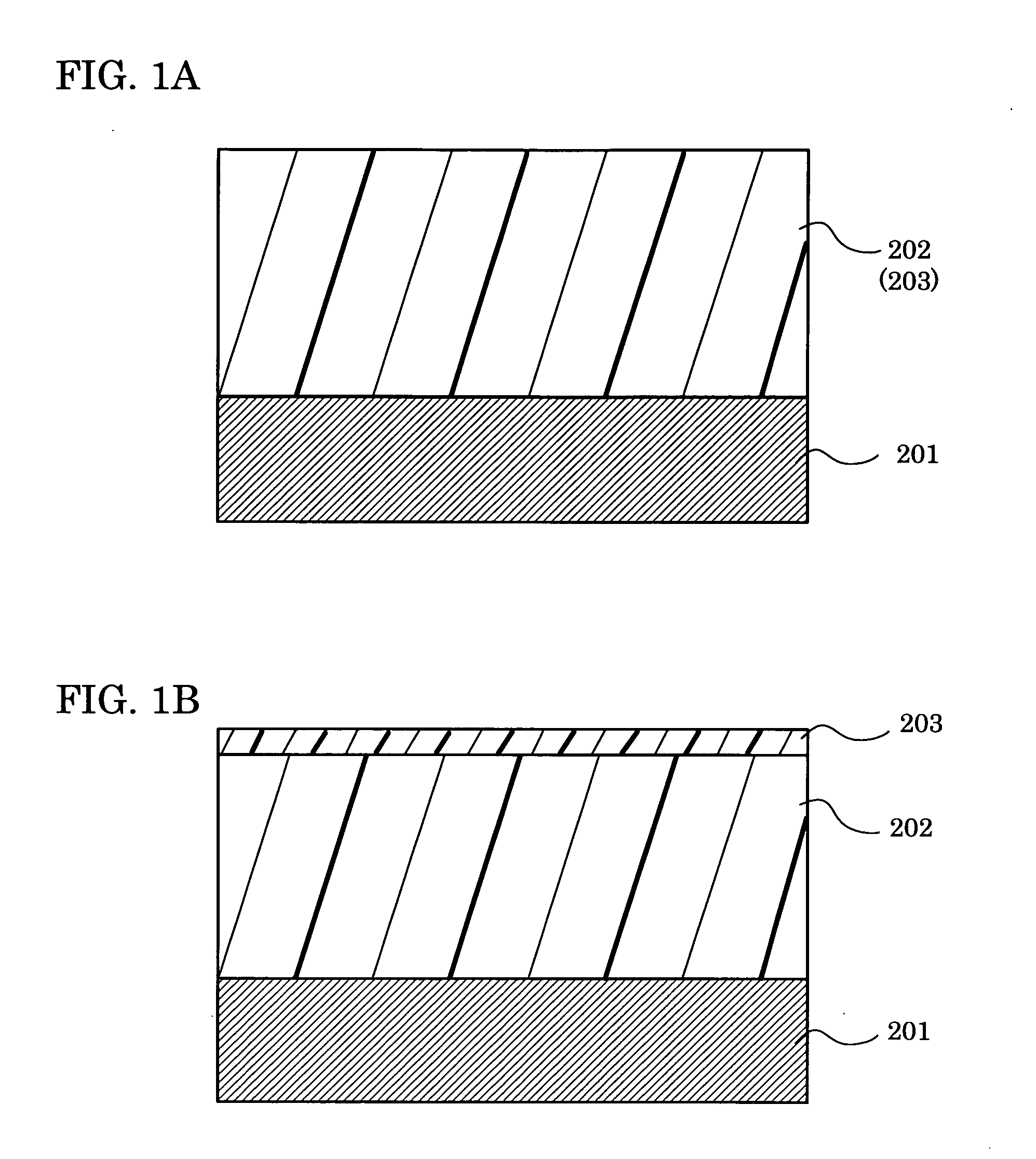
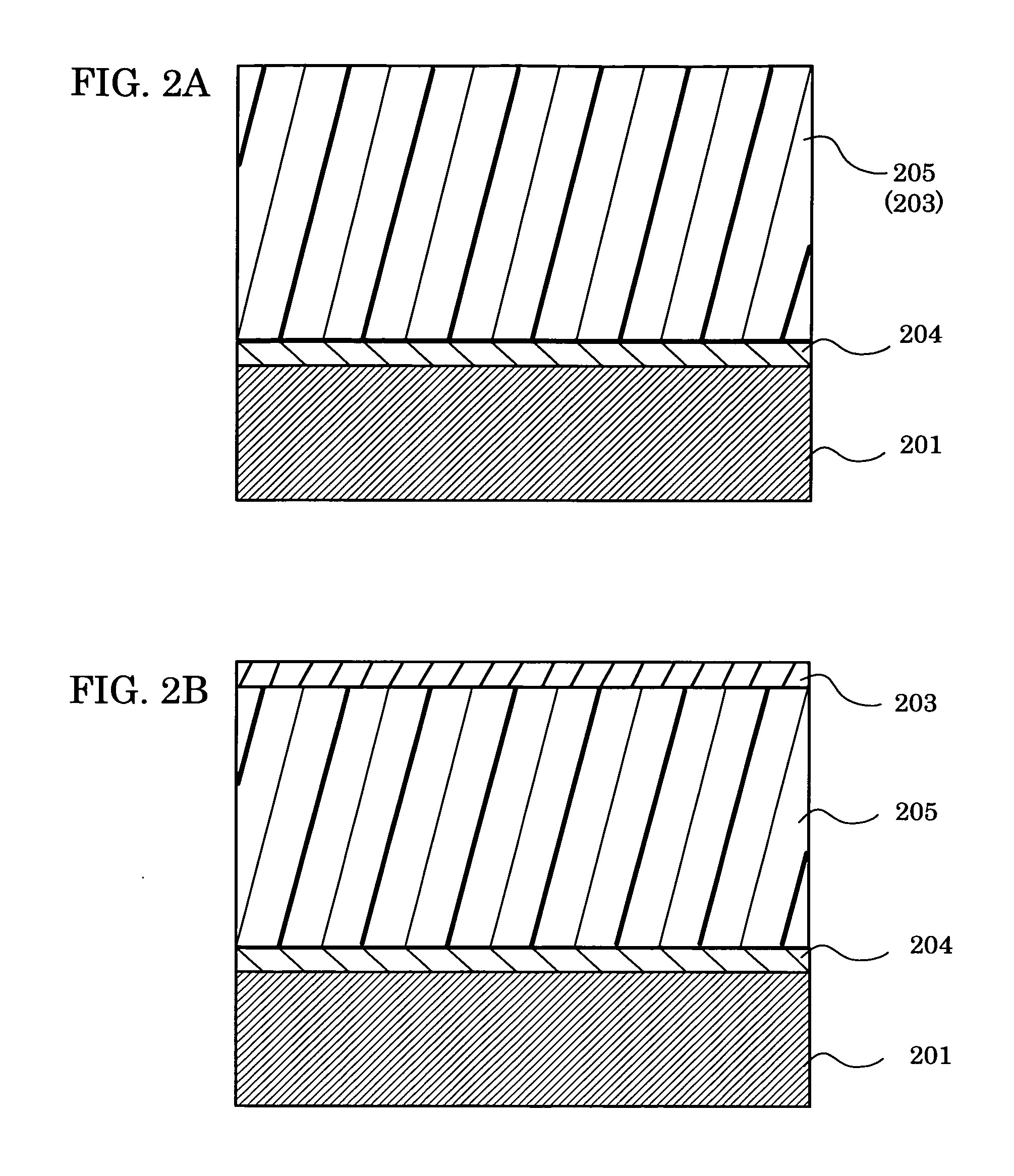
A photoconductor comprising a photosensitive layer disposed on an support, wherein the photosensitive layer has at least a crosslinked layer and the crosslinked layer is produced by curing at least a radical polymerizable monomer having three or more functionalities and no charge transport structure and a radical polymerizable compound having a charge transport structure through irradiating a light energy in an atmosphere having a low oxygen concentration of 0.001 vol % to 2.0 vol %.

Description

BACKGROUND OF THE INVENTION [0001] 1. Field of the Invention [0002] The present invention relates to a photoconductor to which high durability and a high image quality are imparted by disposing in the photoconductor, a photosensitive layer having advantageous film surface properties, high wear resistance and advantageous electrical properties; and a manufacturing method thereof. The present invention relates also to an image forming process, image forming apparatus and process cartridge for the image froming apparatus using the above-noted photoconductor having long life and high performance. [0003] 2. Description of the Related Art [0004] Recently, organic photoconductors (OPC) are widely employed in copiers, facsimiles, laser printers, and composite apparatuses thereof owing to excellent performance and various advantages, in place of conventional inorganic photoconductors. Specific grounds thereof are thought as follows: (i) optical properties such as absorbable wavelength and ab...

Claims


Application Information

Patent Timeline
Patent Type & Authority Applications(United States)
IPC IPC(8): G03G5/05G03G5/06G03G5/07G03G5/147
CPCG03G5/0546G03G5/0589G03G5/071G03G5/0614G03G5/0592G03G5/072G03G5/0732G03G5/074G03G5/0745
Inventor IKUNO, HIROSHITAMURA, HIROSHISUZUKI, TETSUROYANAGAWA, YOSHIKI
Owner RICOH KK
Why Eureka
Try Eureka