Method for characterizing porous low dielectric constant films

a low dielectric constant, film technology, applied in the field of microelectronics, can solve the problems of increased probability of failure, production loss, and difficulty in using techniques

Inactive Publication Date: 2006-01-12
AIR PROD & CHEM INC
View PDF6 Cites 55 Cited by
  • Summary
  • Abstract
  • Description
  • Claims
  • Application Information

AI Technical Summary

Problems solved by technology

However, as the pore size approaches the dimensions of the features on the chip, the probability for failure increases.
Typically, the metal migration is caused by defects in the barrier layers, which allow copper to diffuse into the dielectric layer.
Because these defects may result in production loss, there is a need for measuring the pore size distribution for low k films used for interlevel dielectrics.
However, these techniques may be difficult to use when the materials are in the form of thin films on substrates such as a silicon wafers.
These thin films have too small a total pore volume and surface area to provide sufficient sorption for analysis by volumetric or gravimetric adsorption.
Consequently, certain porosimetric techniques, such as N2 adsorption, mercury intrusion, or quartz crystal microbalances, may lack the sensitivity to characterize porosity in films that are less than 1 μm thick and attached to a 1-mm-thick silicon single-crystal wafer.
Scraping the film off the substrate, however, could alter the pore size distribution.
The use of classical models may limit the sensitivity to the absence of killer pores.
Although the small analytical area of less than 1 mm3 may be appropriate for the microelectronic industry, particularly if it is desirable to “isolate” the presence of defects on a specific location on the wafer, it may be impractical as a quality control tool in identifying whether there are any defects present on an entire wafer.
The XRP method requires the atomic composition of the film to convert electron density to mass density, which usually requires the use of complex techniques such as forward recoil elastic scattering and Rutherford backscattering.

Method used


Image

  • Method for characterizing porous low dielectric constant films
  • Method for characterizing porous low dielectric constant films
  • Method for characterizing porous low dielectric constant films

Examples


example 1

Spin-On Low k Film Using Surfactant as Porogen and BJH / Kelvin as Procedure / Model for Capillary Condensation

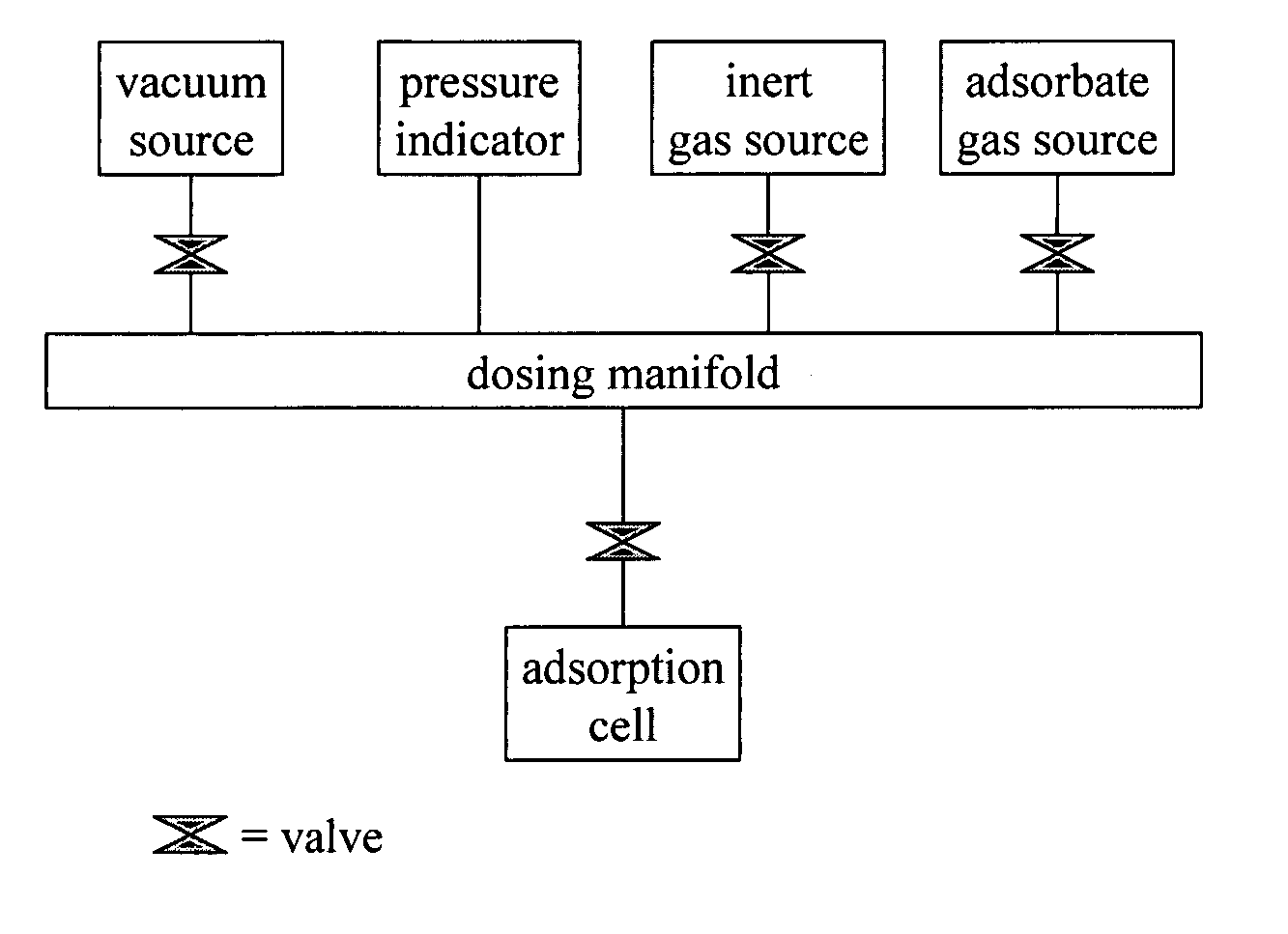
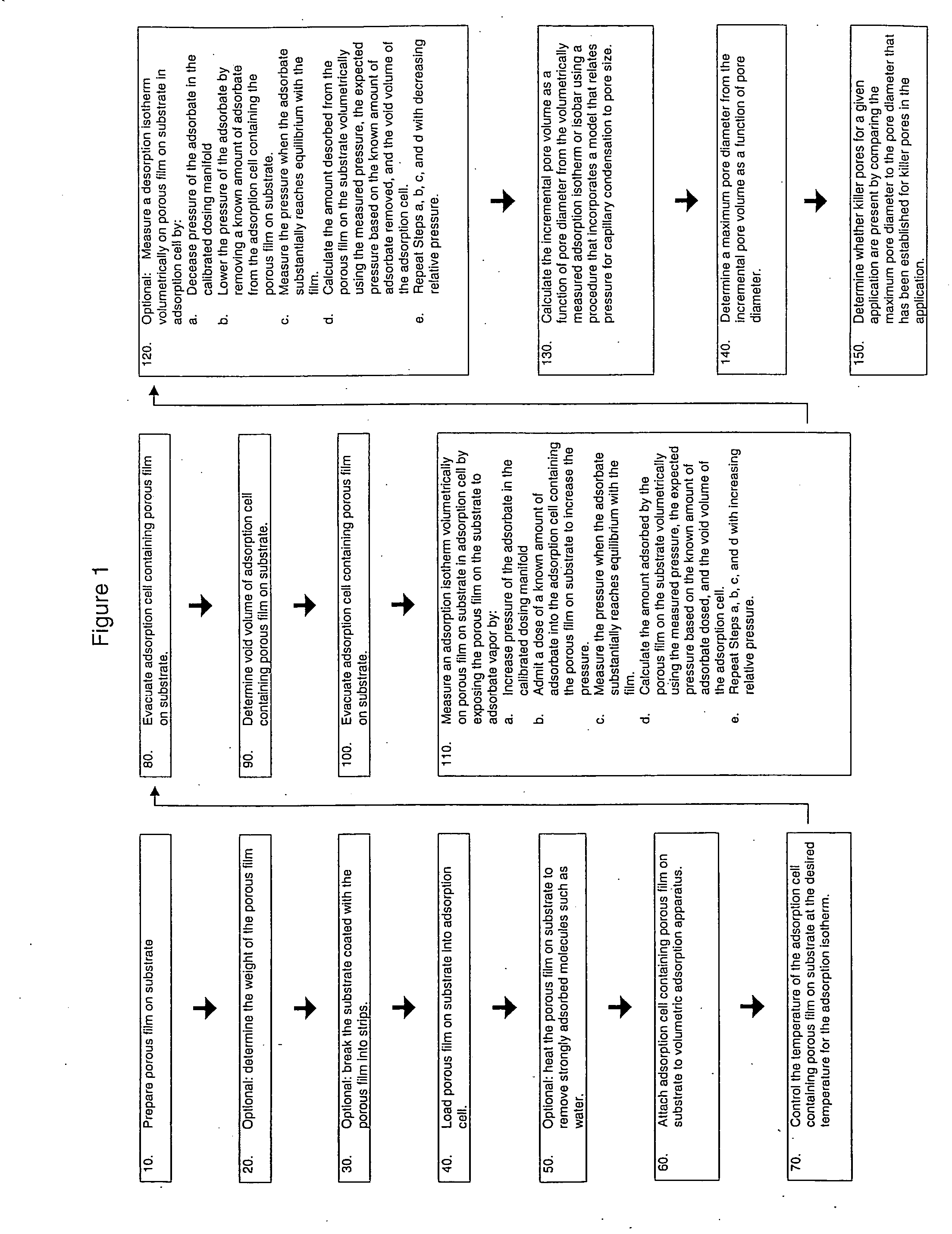
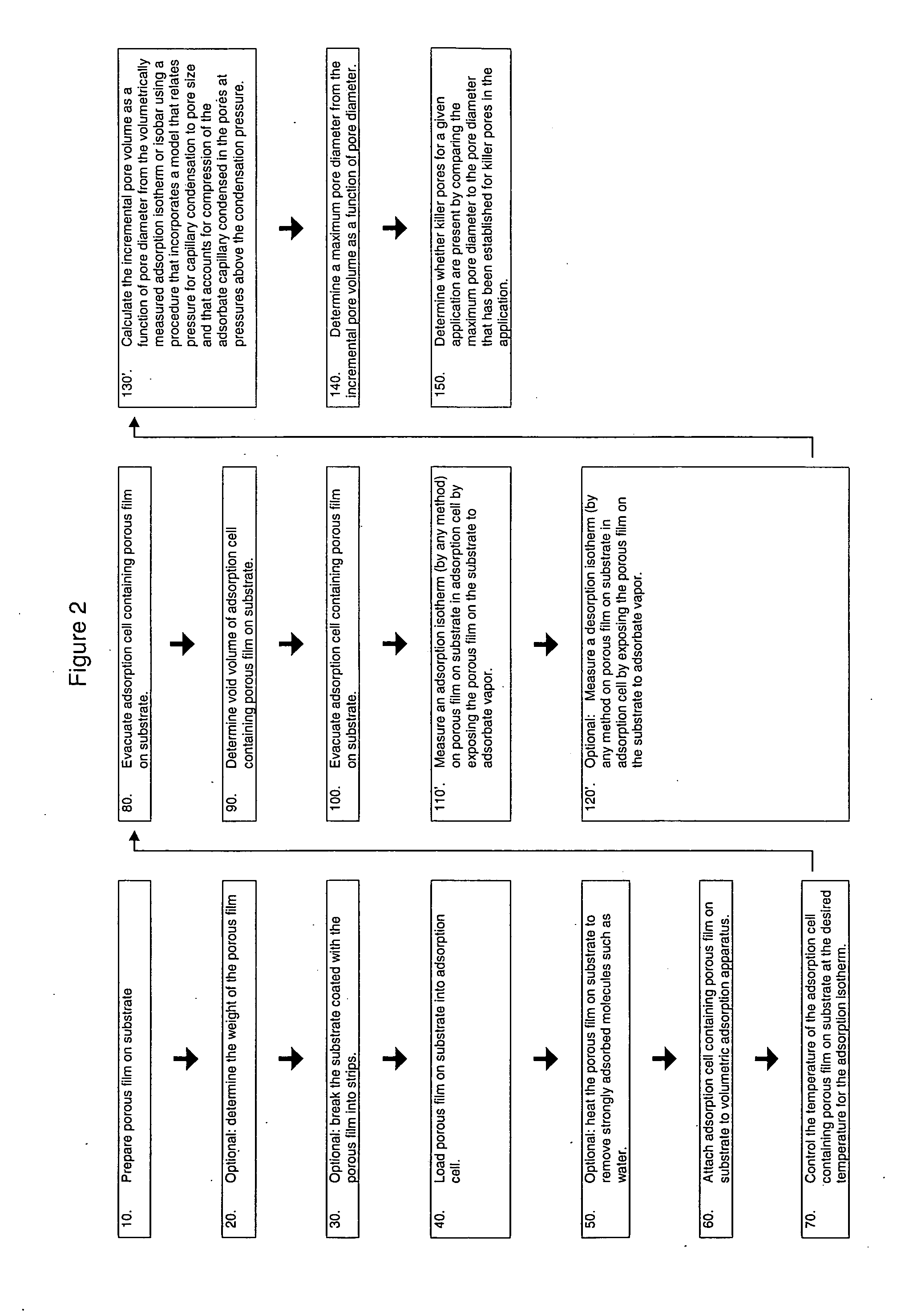
[0113] The following example shows that it is possible to measure adsorption / desorption isotherms volumetrically on a film on a substrate. It also shows a new definition of pore diameter that can be used for determining whether killer pores are present. The film forming mixture was prepared in a high-density polyethylene bottle by adding 50 / 50 by weight methyltriethoxysilane / tetraethoxysilane solution, propylene glycol propyl ether, and surfactant. The mixture was shaken briefly. An aqueous solution of 96 wt % 0.1 M nitric acid and 4 wt % 2.4 wt % aqueous tetramethylammonium hydroxide, was added. The bottle was capped and shaken for 30 to 60 seconds. The solution was aged in the capped bottle at ambient temperature for at least 2 hours.

[0114] A film of the mixture was deposited by spin-coating a 1.2 milliliter (mL) sample on a 4-inch wafer with 0.005-0.020 ohm-cm resistivity ...

example 2

Spin-On Low k Film Using Surfactant as Porogen and GAI / DFT as Procedure / Model for Capillary Condensation

[0130] This example shows the unexpected benefit of DFT over BJH in giving a lower killer pore volume absence detection limit. The samples and isotherms were the same as those used in Example 1.

Calculate the Incremental Pore Volume as a Function of Pore Diameter from the Volumetrically Measured Adsorption Isotherm Using GAI as the Procedure and Incorporating DFT as the Model that Relates Pressure for Capillary Condensation to Pore Size

[0131] Micromeritics ASAP DFT Plus® for Windows, Version 3.00 software, commercially available, was used to calculate the pore size distributions using the N2 adsorption branch of the isotherms at 77 K. The options for the calculations include the choice of model (or kernel of isotherms (to be used in the GAI equation) obtained from the DFT calculations), the extent of regularization (or smoothing), and the data points in the isotherm used for the...


PUM

PropertyMeasurementUnit
dielectric constantaaaaaaaaaa

Abstract

A method and apparatus for determining pore size distribution and / or the presence of at least one killer pore in at least a portion of a porous film deposited upon a substrate are disclosed herein. In one embodiment, there is provided a method for determining pore size distribution comprising: providing the substrate having the film deposited thereupon wherein the film comprises pores and wherein the pores have a first volume; exposing the film to an adsorbate at a temperature and a pressure sufficient to provide condensation of the adsorbate in pores and wherein the pores after the exposing step have a second volume; and measuring the difference between the first and the second volume using a volumetric technique; and calculating the pore size and pore volume using the change in the first and the second volume, the pressure, and a model that relates pressure to pore diameter.

Description

CROSS-REFERENCE TO RELATED APPLICATIONS [0001] This application claims the benefit of U.S. Provisional Application No. 60 / 583,924, filed 28 Jun. 2004.BACKGROUND OF THE INVENTION [0002] There is a continuing desire in the microelectronics industry to increase the circuit density in multilevel integrated circuit devices such as memory and logic chips in order to improve the operating speed and reduce power consumption. In order to continue to reduce the size of devices on integrated circuits, it has become necessary to use insulators having a low dielectric constant (k) to reduce the resistance-capacitance (“RC”) time delay of the interconnect metallization and to prevent capacitive crosstalk between the different levels of metallization. Such low dielectric materials are desirable for premetal dielectric layers and interlevel dielectric layers. [0003] Typical dielectric materials for devices with 180 nm line width are materials with a dielectric constant between about 3.8 and 4.2. As...

Claims


Application Information

Patent Timeline
Patent Type & Authority Applications(United States)
IPC IPC(8): G01N15/08
CPCG01N15/0893
Inventor KITZHOFFER, RONALD JOSEPHWEIGEL, SCOTT JEFFREYCOE, CHARLES GARDNERKIMAK, MICHAEL FRANCISMACDOUGALL, JAMES EDWARDKIRNER, JOHN FRANCIS
Owner AIR PROD & CHEM INC
Why Eureka
Try Eureka