AlGaN/GaN high electron mobility transistor devices

Active Publication Date: 2006-01-12
INTERUNIVERSITAIR MICRO ELECTRONICS CENT (IMEC VZW)
View PDF4 Cites 83 Cited by
  • Summary
  • Abstract
  • Description
  • Claims
  • Application Information

AI Technical Summary

Benefits of technology

[0012] It is desirable to prevent crack appearance in the top AlGaN layer, even for highly strained layers. It is important to note that most of these cracks are believed to occur during the cooling down of the structure. An effect

Problems solved by technology

While necessary and beneficial for the creation of a very high mobility channel in the structure, allowing for operation of high power HEMT devices, it has the drawback in that the separation charges within a wurtzite material are also responsible for the surface charged layer at the top surface of the structure, leading to an increased importance of surface states, compared to zincblend structure materials.
The presence of surface states creates acute problems for achieving the high performance that is theoretically predicted for those devices, as surface states play an important role during device operation.
Another problem in the development of field-effect GaN based transistors is the ohmic contact formation on the group III-nitride surface.
The lack of a good ohmic contact formation on the top layer directly leads to drastic reduction of the device per

Method used


Image

  • AlGaN/GaN high electron mobility transistor devices
  • AlGaN/GaN high electron mobility transistor devices
  • AlGaN/GaN high electron mobility transistor devices

Examples


example 1

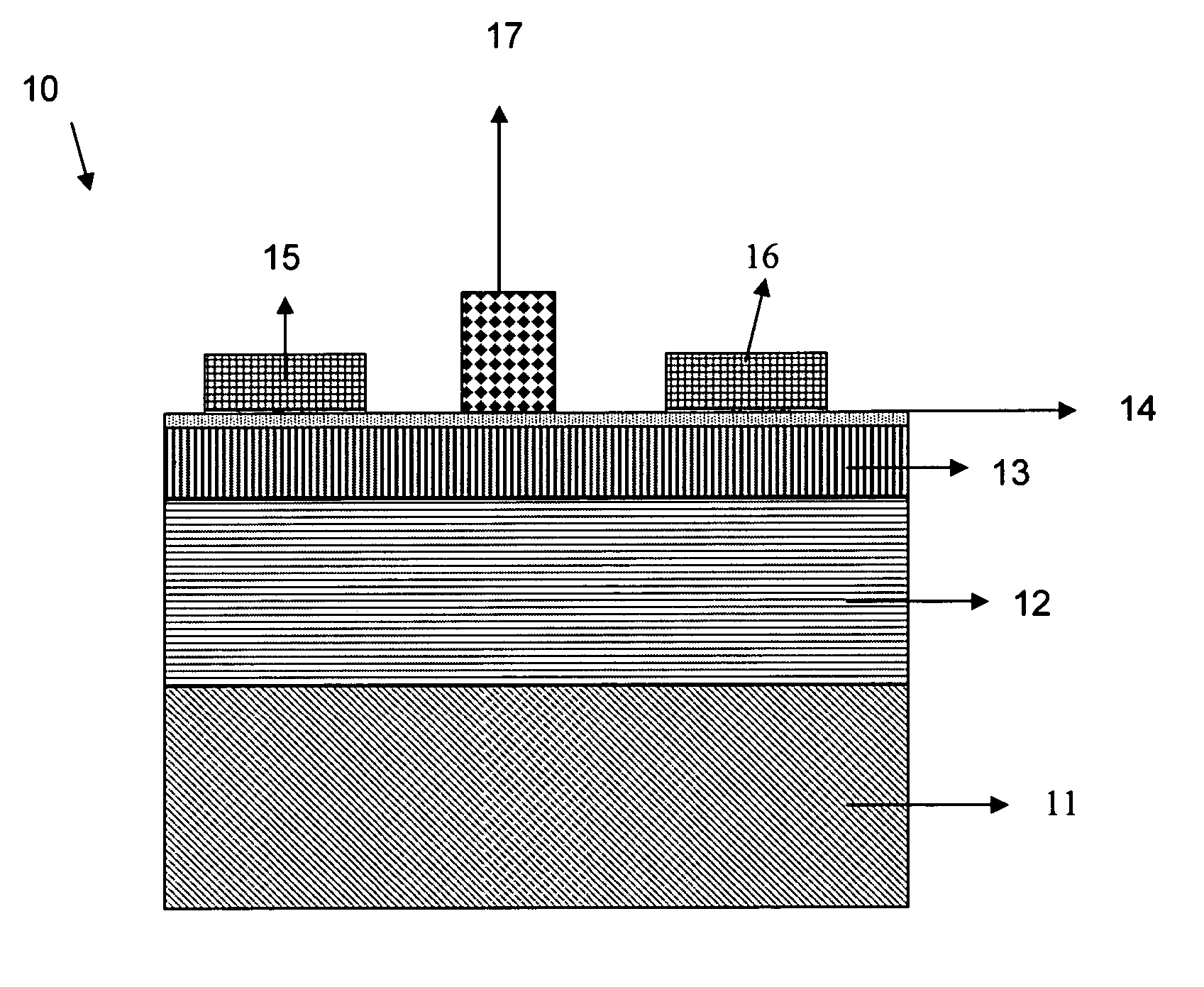
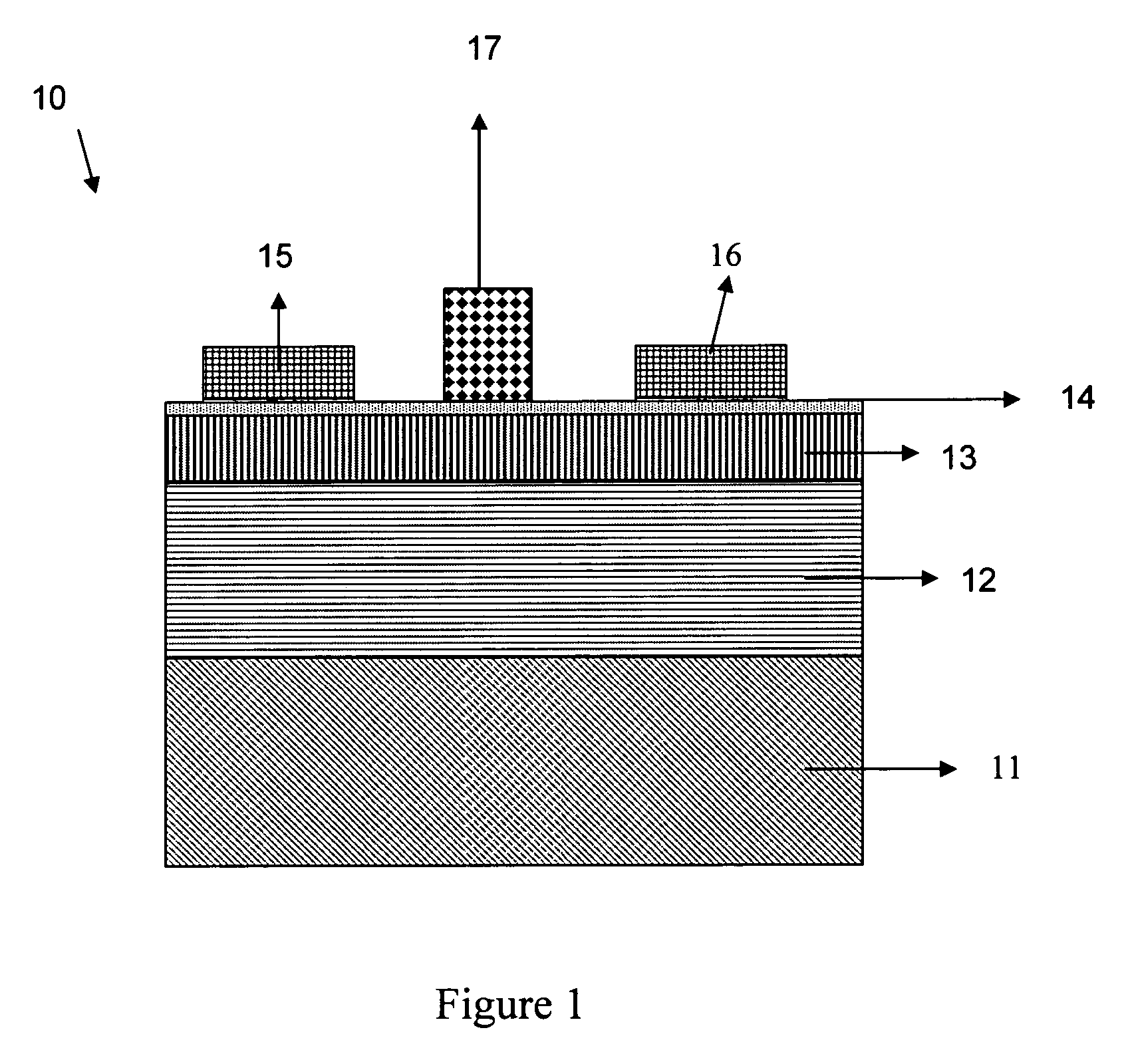
[0175] AlGaN / GaN HEMT structures were grown at low pressure (133.3 mbar (100 Torr)) using Metal Organic Vapor Phase Epitaxy (MOVPE). As starting compounds, trimethyl gallium (TMGa), trimethyl aluminum (TMAl) and ammonia (NH3) were used.

[0176] The metal-organic precursors were transported with hydrogen as carrier gas; the amounts were regulated by means of mass flow controllers and the temperature of the thermostat baths in which the metal organic bubblers are mounted.

[0177] The flow of ammonia was also regulated by means of a mass flow controller and traces of water and oxygen were removed by an in-line filter.

[0178] Additionally, n-type doping of the GaN and (Al,Ga)N layers was achieved by adding silane (SiH4) during growth.

[0179] All gasses were introduced into the reactor via the so-called close-coupled showerhead.

[0180] After degassing the substrate at high temperatures (about 1100° C.), a thin GaN buffer layer was deposited at lower temperature using NH3 and TMGa.

[0181] T...

example 2

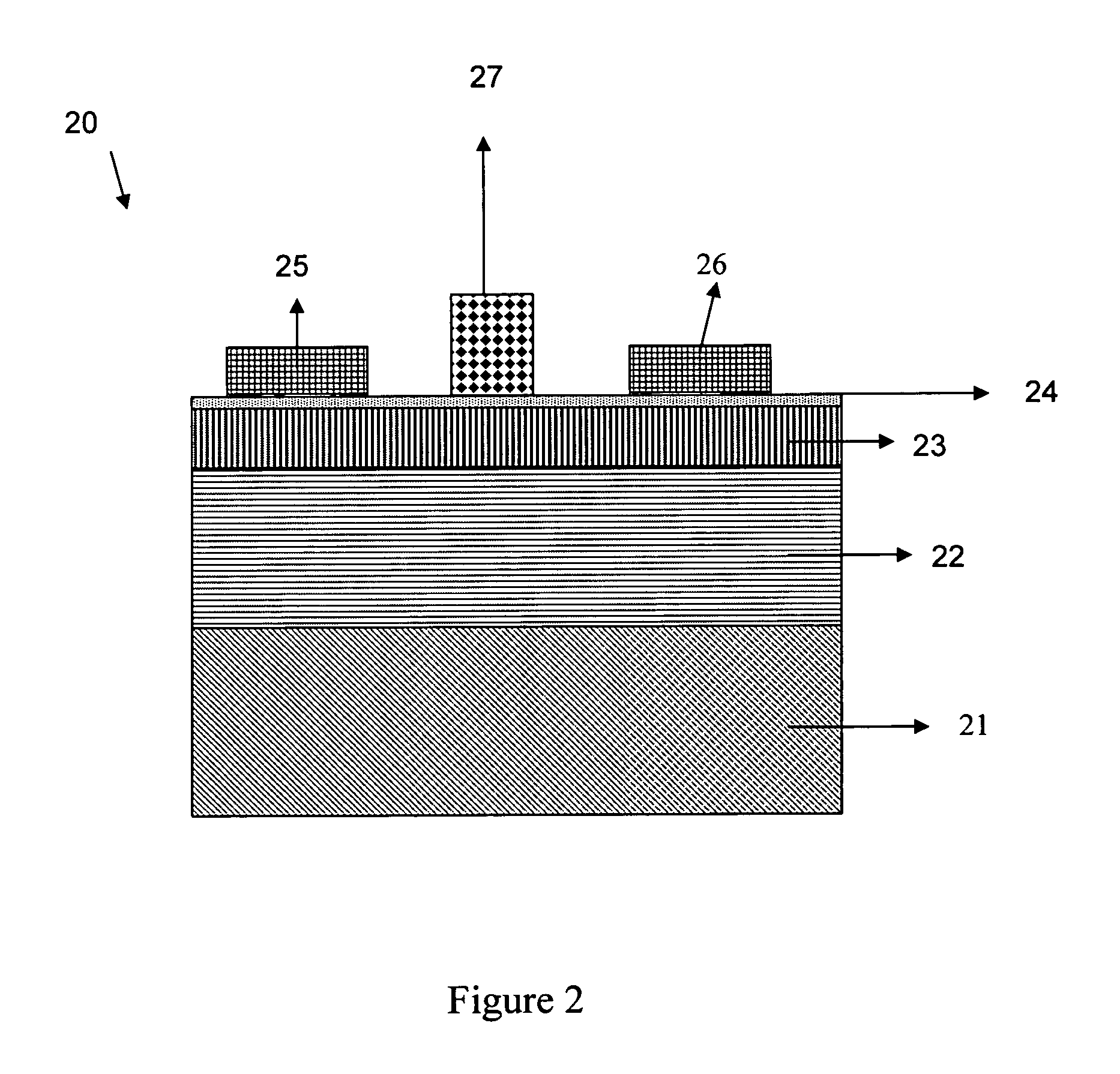
[0184] AlGaN / GaN HEMT structures were grown by MOVPE on [0001] sapphire substrates. A Thomas Swan close-coupled showerhead reactor was used with starting compounds trimethylgallium (TMGa), trimethylaluminum (TMAl), ammonia (NH3), and diluted silane (SiH4, 200 ppm in hydrogen). The silane introduction line was modified in such a way that the amount of silane introduced in the reactor was regulated from the required amount for n-type doping of GaN (a few nmol / min up) to about 1 μmol / min.

[0185] After deposition of a thin GaN nucleation layer at low temperature, a 2.6 μm thick GaN layer was grown at 1020° C. with a reactor pressure of 133.3 mbar (100 Torr). Prior to deposition of the AlGaN, a thin AlN spacer layer was grown at 53.33 mbar (40 Torr) to improve mobility in the 2DEG. Depending on samples, the top AlGaN layer was from 22 to 24 nm thick and the Al content was 30% as determined by High-Resolution X-Ray Diffraction measurements. After growth of the AlGaN layer, the reactor was...


PUM


Abstract

The present invention recites a new method for manufacturing Group III-N field-effect devices, such as HEMT, MOSHFET, MISHFET devices or MESFET devices, grown by Metal-Organic Vapor Phase Expitaxy, with higher performance (power), by covering the surface with a thin SiN layer on the top AlGaN layer, in the reactor where the growth takes place at high temperature, prior cooling down the structure and loading the sample out of the reactor, as well as a method to produce some HEMT transistors on those heterostructures, by depositing the contact on the surface without any removal of the SiN layer by MOCVD. The present invention recites also a device.

Description

CROSS-REFERENCE TO RELATED APPLICATIONS [0001] This application claims priority under 35 U.S.C. § 119(e) to U.S. Provisional Application No. 60 / 584,687, filed Jun. 30, 2004. The above-referenced prior application is incorporated by reference herein in its entirety and is hereby made a portion of this specification.FIELD OF THE INVENTION [0002] The invention relates to the group III-nitride field effect devices, and methods to improve stability of the surface, by passivation of the top surface, as well as to ohmic contact deposition on wide bandgap layers. BACKGROUND OF THE INVENTION [0003] High Electron Mobility Transistors (HEMTs) were first developed in the 1970's and are employed in advanced communications applications, such as microwave circuit applications. The first HEMTs were formed using GaAs and AlGaAs, but new structures using GaN and other materials are becoming of greater importance. The HEMT behaves much like a conventional Field Effect Transistor (FET), and the fabrica...

Claims


Application Information

Patent Timeline
IPC IPC(8): H01L31/0328H01L21/3205
CPCH01L29/2003H01L29/452H01L2924/13063H01L29/7787H01L29/802H01L29/66462
Inventor GERMAIN, MARIANNEDERLUYN, JOFFLEYS, MAARTEN
Owner INTERUNIVERSITAIR MICRO ELECTRONICS CENT (IMEC VZW)
Why Eureka
Try Eureka