Optical amplifier and optical monitor circuit

a monitor circuit and optical amplifier technology, applied in electromagnetic transmission, electromagnetic repeaters, transmission, etc., can solve the problems of input shutdown function, deterioration of control accuracy of optical amplifiers, deterioration of wavelength flatness of signal light power on the reception side, etc., to achieve low cost, simple circuit configuration, and high accuracy

Inactive Publication Date: 2006-02-02
FUJITSU LTD
View PDF8 Cites 36 Cited by
  • Summary
  • Abstract
  • Description
  • Claims
  • Application Information

AI Technical Summary

Benefits of technology

[0013] The present invention has been accomplished in view of the above problems, and has an object to provide at a low cost an optical amplifier and an optical monitor circuit, which are provided with a monitoring function capable of detecting with high accuracy the noise light power, the signal light power and the like, generated when a signal light is amplified, using a simple circuit configuration.
[0016] Further, when the above optical amplifier includes an optical filter device which transmits the signal light in accordance with a previously set transmission wavelength characteristic, on the optical fiber connected to the optical amplification section, the optical filter device is provided with a function as the optical reflection medium. Thus, it becomes possible to monitor the power of the noise light utilizing the existing optical filter device, without the necessity of separately adding a device for noise light monitoring.
[0018] Furthermore, the above optical amplifier may be provided with a control section that corrects the noise light power contained in the optical output power from the optical amplification section based on the total power of the noise lights computed in the computation section to calculate the optical output power of only a signal light component, thereby controlling the optical amplification section according to the calculation result. According to such a configuration, it becomes possible to control the optical amplifier without a substantial influence of the noise light.
[0020] According to such an optical monitor circuit, even in the case where the power of the light in the first wavelength band and the power of the light in the second wavelength band are significantly different from each other as in the power of the signal light and the power of the noise light, by selectively reflecting the light in the low power band at the high reflectance, it becomes possible to monitor the power of such a light with high accuracy.

Problems solved by technology

However, there is a problem in that the wavelength flatness of the signal light power on the reception side is deteriorated due to various factors, such as conditions of optical transmission path, the accumulation of gain wavelength characteristic (for example, tilt, ripple or the like) in an optical amplification repeating station using the rare-earth element doped optical fiber amplifier, the Raman amplifier and the like.
Therefore, as one issue concerning an optical amplifier operation control, there is considered the establishment of technology for controlling an output wavelength characteristic of the optical amplification repeating station (first issue).
Further, in the optical amplifier, an amplified spontaneous emission (ASE) light being a noise component is generated with the optical amplification.
Therefore, in the case of performing a control of the optical amplifier, such as an automatic level control or an automatic gain control, using a typical output monitoring technology in which an output light from the optical amplifier is branched to be received by a light receiver, since the optical power of the ASE light being the noise component is contained together with the signal light in the output light, an influence of the ASE light is reflected in the output monitoring result, thereby deteriorating the control accuracy of the optical amplifier.
Moreover, an input shutdown function (function of detecting no-input of the input signal light power to shut off the pumping light power for the optical amplifier) of the optical amplifier arranged on the downstream is also deteriorated.
Such a problem caused by the ASE light becomes serious, since a generation amount of the ASE light is significantly changed, particularly in a system or the like where the number of signal wavelengths is dynamically changed.
Moreover, in the optical amplifier, there is a problem in that, in a high population inversion state, energy concentrates in a wavelength range having a larger gain coefficient to cause an oscillating operation, and accordingly, the noise component is increased to deteriorate a transmission characteristic.
This oscillation phenomenon of the optical amplifier includes a threshold according to a relationship between a gain of an optical amplification medium and reflection attenuation amounts on the input and output sides of the optical amplification medium, and therefore, the problem as described above is exposed due to factors, such as gain conditions of the optical amplifier, the deterioration of reflection attenuation amounts in optical components.
Therefore, as a further issue concerning the optical amplifier operation control, there is considered the establishment of control technology in which the output light level does not exceed an oscillation threshold in a previously known wavelength range of large gain coefficient (third issue).
Therefore, there is a disadvantage of the complication and high cost of the optical circuit configuration.
Accordingly, there is also a problem in that the photosensitivity is poor and it becomes hard to monitor with desired accuracy the noise light power.
However, according to such a method, it is hard to estimate accurately the value of the power of the noise light generated in the optical amplifier, since the generation amount of the noise light is dynamically changed according to individual differences in components of the optical amplification medium, a change in environment (for example, temperature, humidity or the like), the number of wavelengths of the signal light contained in the WDM light or the like.
Therefore, it becomes impossible to correct accurately the noise light component in the actually monitored optical output power.
Consequently, the control accuracy of the optical amplifier becomes poor, thereby deteriorating the performance and reliability of the WDM optical communication system.

Method used


Image

  • Optical amplifier and optical monitor circuit
  • Optical amplifier and optical monitor circuit
  • Optical amplifier and optical monitor circuit

Examples


first embodiment

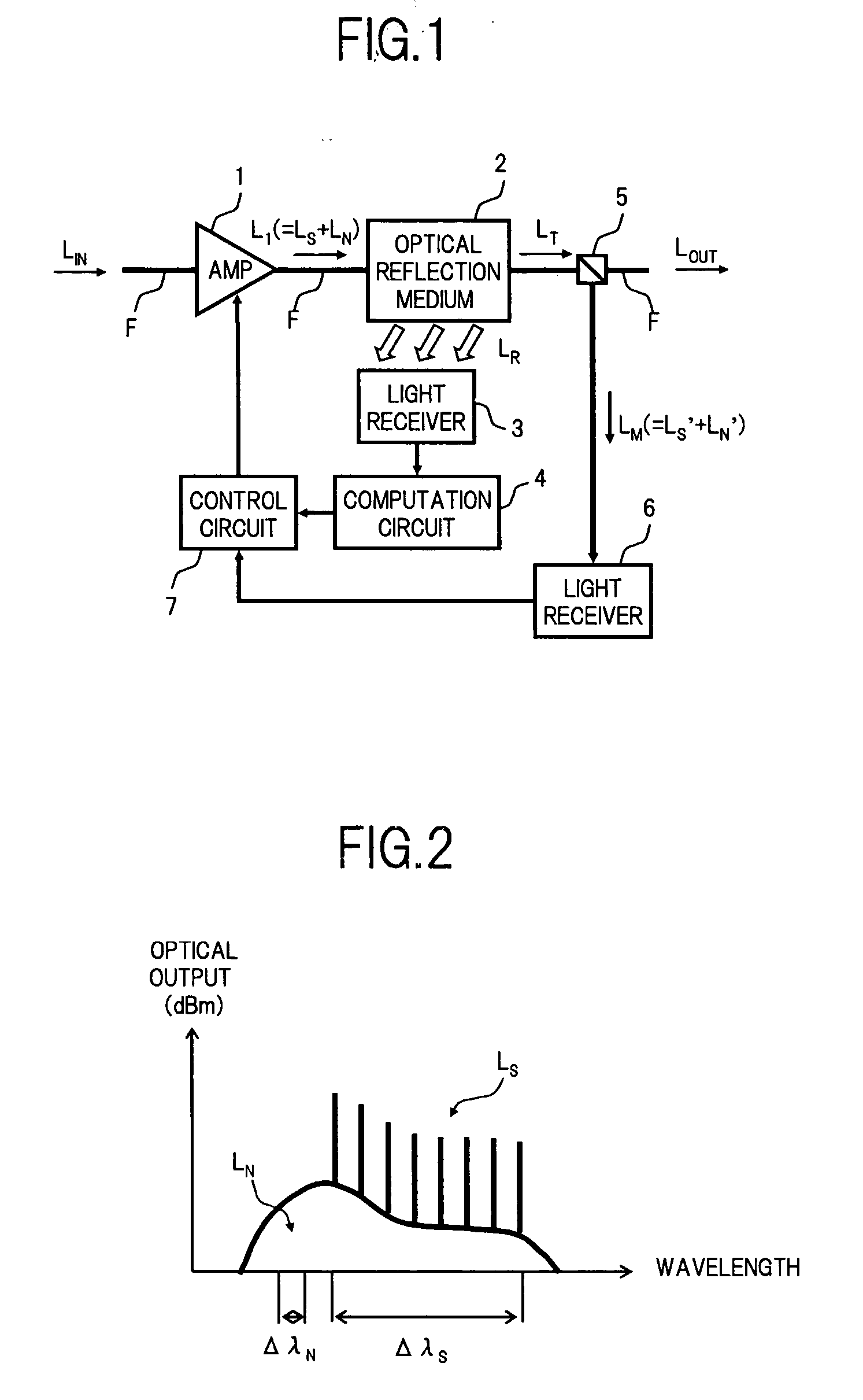
[0035]FIG. 1 is a block diagram showing a configuration of an optical amplifier according to the present invention.

[0036] In FIG. 1, the optical amplifier in the first embodiment comprises, for example, an optical amplifying circuit 1 as an optical amplification section that amplifies an input signal light LIN, an optical reflection medium 2 formed on an optical fiber F connected to the optical amplifying circuit 1, a light receiver 3 as a light receiving section that receives a light reflected to be radiated to the outside of a core of the optical fiber F by the optical reflection medium 2, to detect the power of the radiated light, and a computation circuit 4 as a computation section that computes the total power of a noise light generated in the optical amplifying circuit 1, based on the detection result in the light receiver 3. Further, this optical amplifier includes an optical branching device 5 which branches a part of a light output from the optical amplifying circuit 1 to b...

second embodiment

[0048] Next, the present invention will be described.

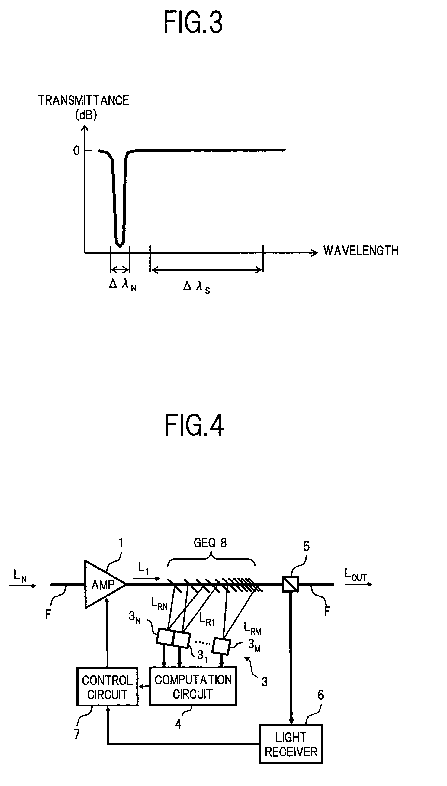
[0049]FIG. 4 is a block diagram showing a configuration of an optical amplifier in the second embodiment. The feature of the optical amplifier in the second embodiment is that a gain equalization optical filter (GEQ) 8 typically provided in a known optical amplifier which collectively amplifies the WDM light also includes a function as the optical reflection medium 2 in the above first embodiment.

[0050] The GEQ 8 is a fiber grating configured by combining a tilted configuration in which a Bragg diffraction grating is formed to be tilted to an axial direction of the optical fiber F and a chirped configuration in which grating spacing of the Bragg diffraction grating is gradually changed along the axial direction of the optical fiber F (to be referred to as a titled and chirped FBG hereunder). This tilted and chirped FBG is designed to have a transmission wavelength characteristic capable of flattening a gain wavelength characteris...

third embodiment

[0079] Next, the present invention will be described.

[0080]FIG. 10 is a block diagram showing a configuration of an optical amplifier in the second embodiment.

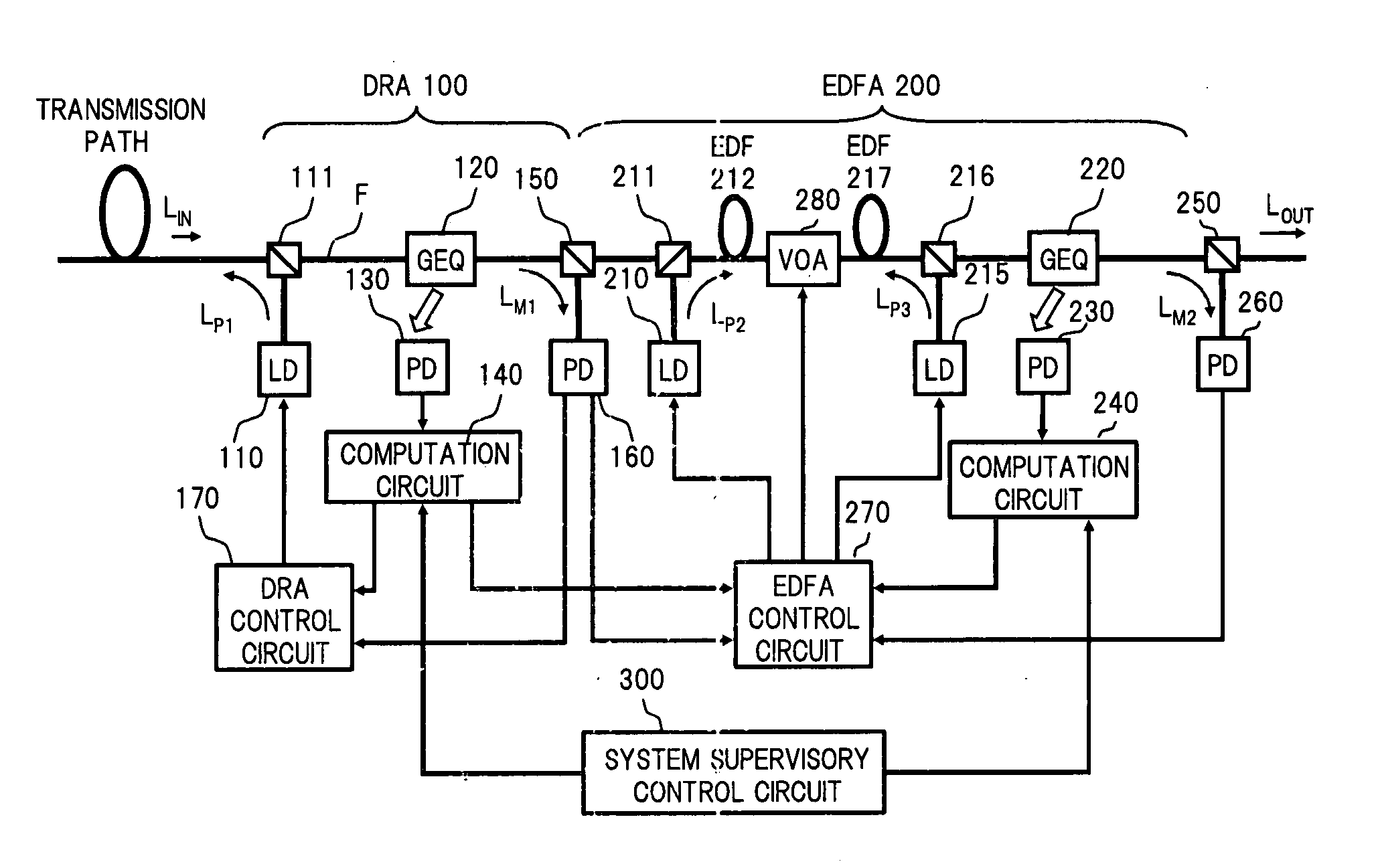
[0081] In FIG. 10, the optical amplifier in the third embodiment is a specific example in the case where the present invention is applied to a configuration in which a distributed Raman amplifier (DRA) 100 and an erbium doped optical fiber amplifier (EDFA) 200 are connected in cascade.

[0082] The DRA 100 on the former stage supplies a Raman amplification pumping light LP1 generated in a pumping light source (LD) 110 to an input side transmission path (optical amplification medium) via an optical multiplexer 111, to amplify a signal light being propagated through the transmission path due to a Raman effect. A noise light is generated with the Raman amplification of the signal light in the transmission path, and this noise light passes through the optical multiplexer 111 together with the Raman amplified signal light, to be inp...


PUM


Abstract

An optical amplifier of the present invention comprises: an optical amplifying circuit which amplifies a signal light; an optical reflection medium which is disposed on an optical fiber connected to the optical amplifying circuit and is capable of reflecting a noise light which exists in a predetermined wavelength range outside a signal band, among noise lights generated in said optical amplifying circuit, to radiate the reflected noise light to the outside of a core of the optical fiber; a light receiver which receives the noise light reflected to be radiated to the outside of the core of the optical fiber by the optical reflection medium, to detect the power of the noise light; and a computation circuit which computes the total power of the noise lights generated in the optical amplifying circuit based on the detection result of the light receiver. Thus, it is possible to provide at a low cost an optical amplifier provided with a monitoring function capable of detecting high accurately, with a simple optical circuit configuration, the noise light power and the like generated when the signal light is amplified.

Description

BACKGROUND OF THE INVENTION [0001] 1. Field of the Invention [0002] The present invention relates to an optical amplifier and an optical monitor circuit, which are mainly utilized for optical communications, and in particular, relates to an optical amplifier and an optical monitor circuit, which are provided with a monitoring function of detecting the power of noise light and the like generated when a signal light is amplified. [0003] 2. Description of the Related Art [0004] An optical amplifier is one of key components for realizing the long distance and large capacity of an optical communication system. Optical amplifiers are classified into a laser amplifier using the stimulated emission from a population inversion medium and an amplifier based on a non-linear optical effect such as Raman scattering, Brillouin scattering or the like. Further, the laser amplifier includes a rare-earth element doped fiber amplifier and a semiconductor laser amplifier using a semiconductor amplifica...

Claims


Application Information

Patent Timeline
Patent Type & Authority Applications(United States)
IPC IPC(8): H04B10/12H01S3/067H01S3/10H01S3/131H01S3/23H04B10/07H04B10/29H04B10/291
CPCH01S3/06754H01S3/1305H04B10/2941H04B10/07955H04B10/071
Inventor ONAKA, MIKIHAYASHI, ETSUKOONAKA, HIROSHI
Owner FUJITSU LTD
Why Eureka
Try Eureka