Autologous platelet gel having beneficial geometric shapes and methods of making the same

a technology of platelet gel and geometric shape, which is applied in the field of centrifugal separation, can solve the problems of large extracorporeal volume (i.e., the amount of blood that is out of the donor at any given time during the process), difficult or impossible to use discontinuous systems on people, and difficult to control the hematocrit of the final produ

Inactive Publication Date: 2006-02-09
VERMEER MFG CO +1
View PDF45 Cites 19 Cited by
  • Summary
  • Abstract
  • Description
  • Claims
  • Application Information

AI Technical Summary

Benefits of technology

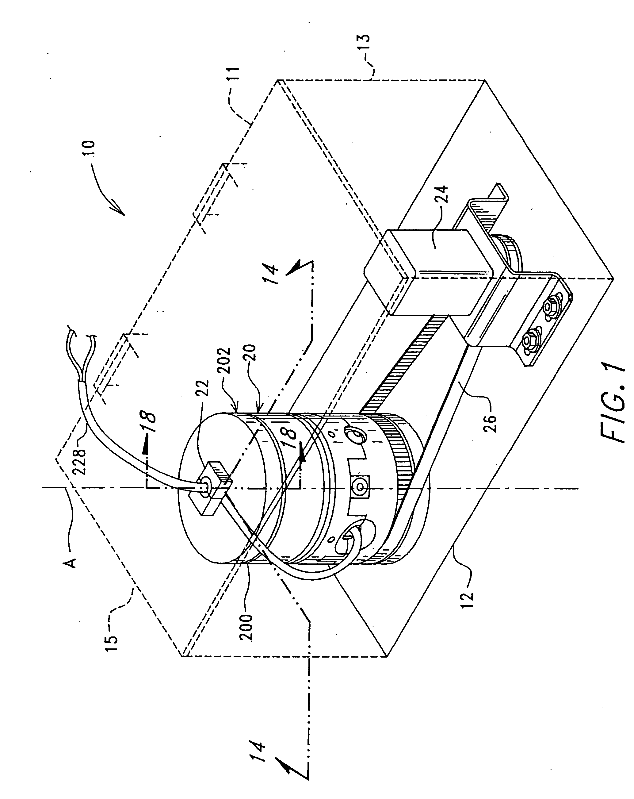
[0049] Another object of this invention is to provide a portable centrifuge containing a disposable centrifuge bag that maximizes the amount of a predetermined blood fraction that can be harvested from an aliquot of blood that is of greater volume than the capacity of the disposable centrifuge bag.
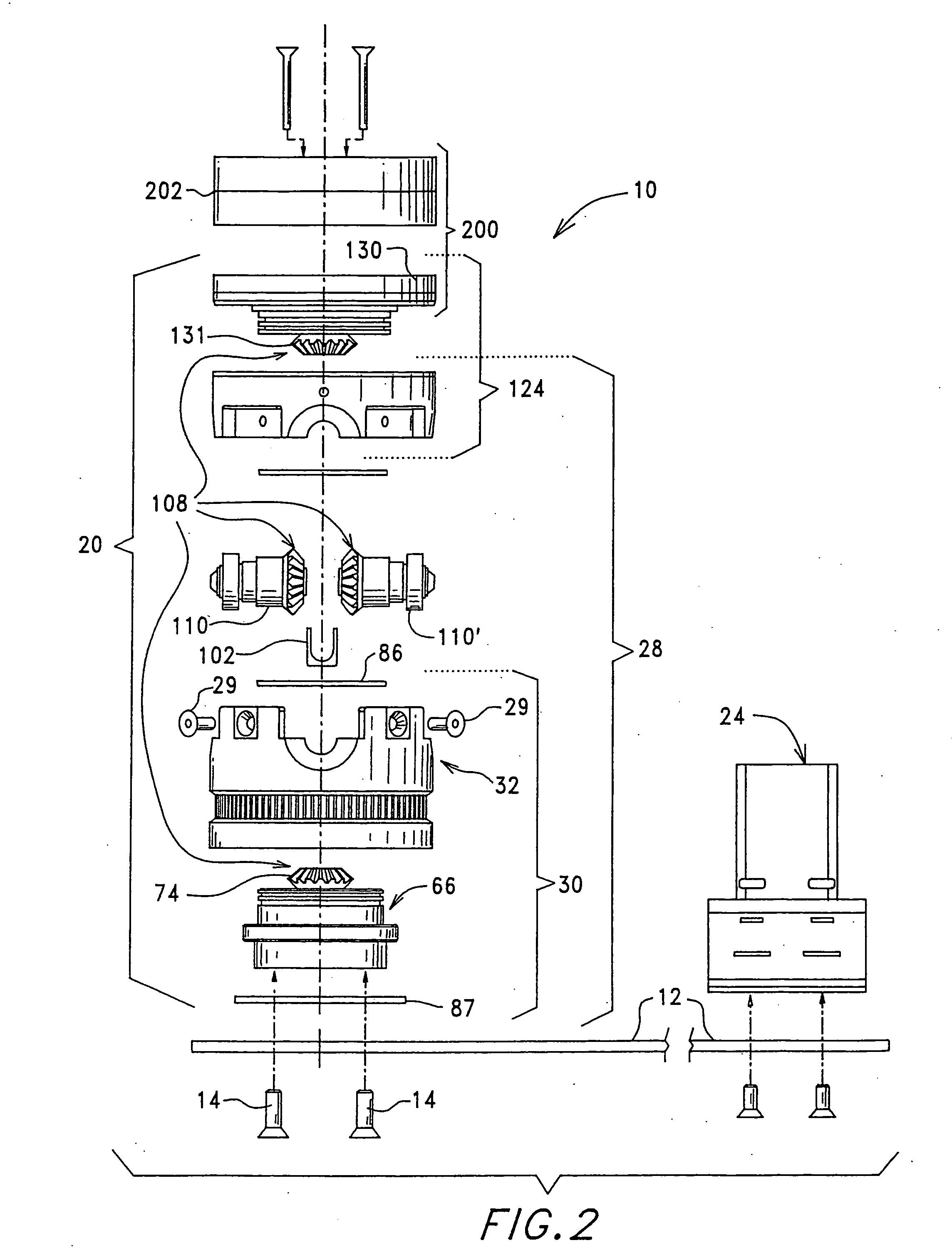
[0062] It is yet another object of the present invention to provide a centrifuge having an internal lead drive mechanism allowing for a compact size.
[0065] Another object of the present invention is to provide an autologous platelet gel wherein the risks associated with the use of bovine and recombinant human thrombin are eliminated.

Problems solved by technology

Discontinuous-flow systems have the advantage that the rotors are relatively small in diameter but have the disadvantage that the extracorporeal volume (i.e., the amount of blood that is out of the donor at any given time during the process) is large.
This, in turn, makes it difficult or impossible to use discontinuous systems on people whose size and weight will not permit the drawing of the amount of blood required to fill the rotor.
Because the bowls in these systems are rigid and have a fixed volume, however, it is difficult to control the hematocrit of the final product, particularly if the amount of blood salvaged is insufficient to fill the bowl with red blood cells.
The McMannis, et al., system takes up a fairly large amount of space, and its flexible pancake-shaped rotor is awkward to handle.
The McMannis, et al., system does not permit the fluid medium to flow into and out of the processing bag at the same time, nor does it permit fluid medium to be pulled out of the processing bag by suction.
Although continuous-flow systems have the advantage that the amount of blood that must be outside the donor or patient can be relatively small, they have the disadvantage that the diameter of the rotor is large.
These systems are, as a consequence, large.
Furthermore, they are complicated to set up and use.
One drawback present in the above-described continuous-flow systems has been their use of a rotating seal or coupling element between that portion of the system carried by the centrifuge rotor and that portion of the system which remains stationary.
While such rotating seals have provided generally satisfactory performance, they have been expensive to manufacture and have unnecessarily added to the cost of the flow systems.
Furthermore, such rotating seals introduce an additional component into the system which if defective can cause contamination of the blood being processed.
The continuous-flow systems described above are large and expensive units that are not intended to be portable.
Further, they are also an order of magnitude more expensive than a standard, multi-container blood collection set.
Nevertheless, the whole process remains laborious and requires the separation to occur within a certain time frame to guarantee the quality of the blood components.
This complicates the logistics, especially considering that most blood donations are performed in decentralized locations where no batch processing capabilities exist.
However, the complexity and costs of haemapheresis systems preclude their use by transfusion centers for routine whole blood collection.
The bag comprises a single inlet / outlet tubing for the introduction and removal of fluids to the bag, and consequently cannot be used in a continual, on-line process.
Moreover, the processing bag has a the disadvantage of having 650 milliliter capacity, which makes the McMannis, et al., device difficult to use as a blood processing device.
Despite the effectiveness and successful use of fibrin glue by medical practitioners in Europe, neither fibrin glue nor its essential components fibrinogen and thrombin are widely used in the United States.
In addition, the more recent appearance of other lipid-enveloped viruses such as HIV, associated with AIDS, cytomegalovirus (CMV), as well as Epstein-Barr virus and the herpes simplex viruses in fibrinogen preparations makes it unlikely that there will be a change in this policy in the foreseeable future.
The above patents by Rose, et al., and Marx, and the technical paper by Berruyer, et al. each disclose methods for preparing fibrin sealants; however, each of these methods suffer disadvantages associated with the use of bovine thrombin as the activating agent.
A serious and life threatening consequence associated with the use of fibrin glues comprising bovine thrombin is that patients have been reported to have a bleeding diathesis after receiving topical bovine thrombin.
This complication occurs when patients develop antibodies to the bovine factor V in the relatively impure bovine thrombin preparations.
These antibodies cross-react with human factor V, thereby causing a factor V deficiency that can be sufficiently severe to induce bleeding and even death.
Further disadvantages associated with the methods disclosed by Marx and Rose, et al. are that the cryoprecipitate preparations require a large time and monetary commitment to prepare.
A further disadvantage associated with the methods previously disclosed is that while human thrombin is contemplated for use as an activator, human thrombin is not available for clinical use and there is no evidence that patients will not have an antigenic response to human thrombin.
A second difficulty with thrombin is that it is autocatalytic, that is, it tends to self-destruct, making handling and prolonged storage a problem.

Method used


Image

  • Autologous platelet gel having beneficial geometric shapes and methods of making the same
  • Autologous platelet gel having beneficial geometric shapes and methods of making the same
  • Autologous platelet gel having beneficial geometric shapes and methods of making the same

Examples


example 1

Preparation of Bioadhesive Sealant Composition Using Platelet Rich Plasma and Serum

[0285] 6 cc's of platelet rich plasma are drawn into receiving chamber 961 and 3 cc's per PRP or PPP are drawn into receiving chamber 957 which further contains 0.33 cc's of 10% calcium chloride and glass wool. Clotting of the contents will occur in two to eight minutes in receiving chamber 957. The clot is then squeezed through optional filter 958 and the serum, produced therefrom, is added to the platelet rich plasma contained in receiving chamber 961 by either mixing or spraying the two components. The platelet rich plasma and the serum will gel within approximately three minutes.

[0286] The application of the gel using the syringe-type devices 902 as described above maybe less than desirable for may applications. Consequently, in an alternate embodiment the inactive blood component and thrombin can be mixed and / or injected into a mold having a desired geometric shape. The mold may be constructed ...


PUM

PropertyMeasurementUnit
volumeaaaaaaaaaa
volumeaaaaaaaaaa
temperatureaaaaaaaaaa

Abstract

The present invention relates to the production of platelet gels formed into beneficial geometric shapes. Specifically the present invention provides a simpler way to introduce platelet gel for specific uses, such as into the cavity of a gum left after a tooth extraction. Molds of predetermined shapes are provided for forming the desired shape.

Description

BACKGROUND OF THE INVENTION [0001] 1. Field of the Invention [0002] This invention relates to novel methods, devices and apparatuses for the centrifugal separation of a liquid into its components of varying specific gravities, and is more particularly directed toward a blood separation device useful, for example, in the separation of blood components for use in various therapeutic regimens. [0003] 2. Description of the State of Art [0004] Centrifugation utilizes the principle that particles suspended in solution will assume a particular radial position within the centrifuge rotor based upon their respective densities and will therefore separate when the centrifuge is rotated at an appropriate angular velocity for an appropriate period of time. Centrifugal liquid processing systems have found applications in a wide variety of fields. For example, centrifugation is widely used in blood separation techniques to separate blood into its component parts, that is, red blood cells, platelet...

Claims


Application Information

Patent Timeline
Patent Type & Authority Applications(United States)
IPC IPC(8): A61K35/14A61L24/00A61L26/00A61M1/36
CPCA61L24/0005A61L26/0057A61M1/3693A61M1/3696A61M2202/0427A61M2205/331A61M2202/0415A61M1/3616
Inventor DOLECEK, VICTOR D.
Owner VERMEER MFG CO
Why Eureka
Try Eureka