High efficiency power conversion circuits

a power conversion circuit and high efficiency technology, applied in the field of high frequency switched mode electronic power converters, can solve the problems of large switching loss, low cost competitiveness of silicon devices, and inability to gain wide acceptance of high-volume commercial power supplies, so as to reduce the volume of total magnetics, reduce winding voltage stresses and semiconductor component stresses, and high voltage handling capability

Inactive Publication Date: 2006-03-23
TECHN WITTS
View PDF4 Cites 45 Cited by
  • Summary
  • Abstract
  • Description
  • Claims
  • Application Information

AI Technical Summary

Benefits of technology

[0008] An object of the subject invention is to reveal a composite high voltage schottky rectifier that combines the low forward voltage properties of the schottky rectifier with the high voltage handling capability of a junction rectifier.
[0009] Another object of the subject invention is to reveal primary switching networks that reduce winding voltage stresses and semiconductor component stresses by comparison to a half bridge switching network.
[0010] Another object of the subject invention is to reveal a technique for achieving multiple independently regulated output voltages with reduced total magnetics volume.
[0011] Another object of the subject invention is to reveal a simple capacitor coupled gate drive circuit that is tolerant of voltage variations at the source terminal of the high side switch during the on time of the high side switch.
[0012] Further objects and advantages of my invention will become apparent from a consideration of the drawings and ensuing description.
[0013] These and other objects of the invention are provided by novel circuit techniques that combine a schottky barrier rectifier with a high voltage power mosfet to achieve a composite schottky rectifier with a lower forward voltage than can be achieved with a junction rectifier and a higher breakdown voltage than can be achieved with a schottky diode. Also revealed are primary switching circuits that provide significantly reduced voltage stresses to both power semiconductors and magnetic windings so that planar magnetic circuit elements become more practical. Also revealed are new circuit structures for achieving independently regulated outputs in a multi-output power supply with reduced magnetics volume. Also revealed is a simple capacitor coupled floating drive circuit that is tolerant of voltage variations at the terminals of the high side switch.

Problems solved by technology

There are some new material technologies that are just beginning to emerge, but, in general, these are not cost competitive with silicon devices and have not gained wide acceptance in high volume commercial power supplies.
Junction rectifiers are available for low voltage applications but are not commonly used because schottky barrier types offer much lower forward voltage and do not have the charge storage effects of junction rectifiers which can result in large switching losses during the turn on transition of the main switch.
One of the problems of the FIG. 13 circuit is that the on voltage of the composite power mosfet can never be less than the forward voltage of the schottky rectifier D1.
In off line power converters the magnetic circuit elements generally also drive the skyline dimension, but planar magnetics have not gained any significant commercial acceptance in off line power supplies because off line power supplies generally require a larger step down ratio and more primary turns are required to accommodate the higher voltages.
More primary turns imply more winding layers which add to the cost of the magnetic circuit elements.
This was often an application for magnetic amplifiers, but magnetic amplifiers have become less popular as switching frequencies have risen and silicon semiconductor prices have fallen.
The disadvantage of the FIG. 18 circuit is that the second output is not independently regulated and two secondary windings are required on the main transformer.
This floating drive circuit works well where the input source voltage is invariant, but the circuit can change state if there are voltage variations of the input source during the time that the switch MAUX is turned on causing erratic operation, power losses, and, in some cases, component failure.

Method used


Image

  • High efficiency power conversion circuits
  • High efficiency power conversion circuits
  • High efficiency power conversion circuits

Examples


Embodiment Construction

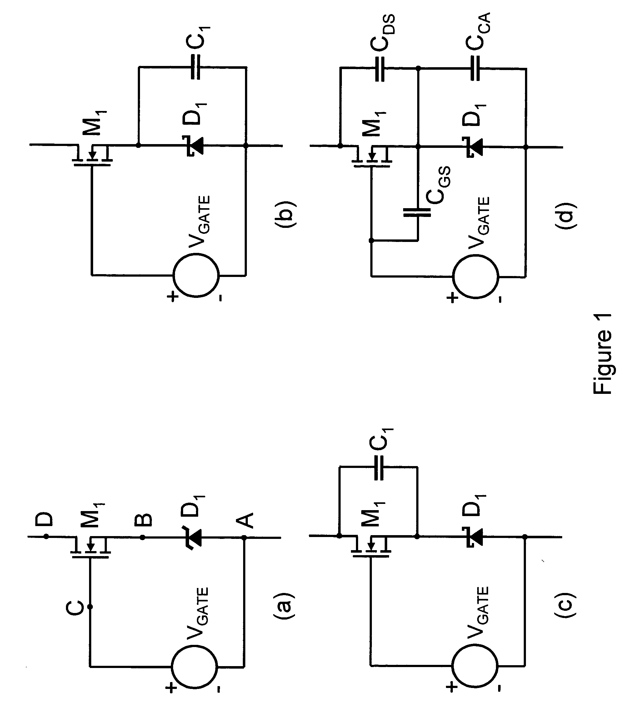
[0075]FIG. 1(a) illustrates a composite high voltage schottky rectifier circuit with its three essential components, a low voltage schottky diode, a dc gate voltage source, and a high voltage power mosfet. FIG. 1(d) illustrates the same circuit with its intrinsic parasitic capacitances. The intrinsic parasitic capacitances of consequence include the schottky diode capacitance, CCA, the gate source capacitance of the power mosfet, CGS, and the drain source capacitance of the power mosfet, CDS. Each of these intrinsic parasitic capacitances are voltage dependent, being larger in capacitance with lower applied voltage and smaller in capacitance at higher applied voltage. The power mosfet also has a drain gate parasitic capacitance which is not illustrated because its effects are insignificant and inconsequential. In a conducting state the schottky diode is forward biased and a voltage equal to the gate voltage source plus the forward voltage of the schottky diode is applied between the...


PUM


Abstract

A composite high voltage schottky rectifier is revealed that provides a forward voltage slightly larger than a low voltage schottky rectifier combined with a high voltage breakdown capability. The composite rectifier can be formed from the combination of a low voltage schottky rectifier, a high voltage mosfet, and a few small passive components. A quarter bridge primary switching network similar in some ways to a half bridge primary switching network is revealed. The quarter bridge network consists of four switches with voltage stress equal to half the line voltage and the network applies one quarter of the line voltage to a primary magnetic circuit element network thereby reducing the number of primary winding turns required to one quarter by comparison to a common full bridge network. A synchronously switched buck post regulator is revealed for multi-output forward converters. The synchronously switched buck post regulator accomplishes precise independent load regulation for each output and reduced magnetics volume by using a coupled inductor with a common core for all outputs plus a second smaller inductor for each output except the highest voltage output. An improved capacitor coupled floating gate drive circuit is revealed that provides an effective drive mechanism for a floating or high side switch without the use of level shifting circuits or magnetic coupling. The capacitor coupled floating gate drive circuit is an improvement over prior art capacitor coupled floating gate drive circuits in that the new circuit uses a positive current feedback mechanism to reject slowly changing voltage variations that cause unintentional switch state changes in prior art capacitor coupled floating gate drive circuits.

Description

BACKGROUND OF THE INVENTION [0001] 1. Field of the Invention [0002] The subject invention generally pertains to electronic power conversion circuits, and more specifically to high frequency, switched mode electronic power converters. Some of the subject matter of this application was first revealed in patent application Ser. No. 10 / 137,908. Some of the subject matter of this application was first revealed in Disclosure Document Number 527396. [0003] 2. Description of Related Art [0004] In modern commercial power electronic circuits passive rectifiers are generally composed of silicon. For low voltage applications schottky barrier rectifier types dominate and in higher voltage applications ultra-fast junction rectifiers dominate. There are some new material technologies that are just beginning to emerge, but, in general, these are not cost competitive with silicon devices and have not gained wide acceptance in high volume commercial power supplies. Junction rectifiers are available f...

Claims


Application Information

Patent Timeline
Patent Type & Authority Applications(United States)
IPC IPC(8): H02M3/335
CPCH02M3/1588H02M3/33592Y02B70/1475Y02B70/1466H03K17/567Y02B70/10H02M1/0058
Inventor WITTENBREDER, ERNEST H. JR.
Owner TECHN WITTS
Why Eureka
Try Eureka