Fluorescent lamp and method of manufacturing same

a technology of fluorescent lamps and fluorescent lamps, which is applied in the manufacture of electric discharge tubes/lamps, discharge tubes luminescent screens, electrode systems, etc., can solve the problems of reducing the life of electrodes, reducing the efficiency of heat conduction, and reducing the electrode life, etc., to achieve high melting point, low resistance, and high thermal conductivity

Inactive Publication Date: 2006-05-11
FOUND FOR ADVANCEMENT OF INT SCI
View PDF5 Cites 11 Cited by
  • Summary
  • Abstract
  • Description
  • Claims
  • Application Information

AI Technical Summary

Benefits of technology

[0023] It is desirable that at least the open tip portion of the electron emitting electrode having the foregoing shape be formed by using a mixture of at least one ma...

Problems solved by technology

However, only by applying the electron emission material to the inner surface of the hollow cathode as shown in Reference Document 1, since the thermal conductivity of the electrode material is poor, La2O3 or the like being an electron emission substance evaporates to reduce the electrode life.
Further, it has also been found that since the lead wire for supplying a voltage to the electrode is joined to the electrode by welding, a thermal resistance is generated at the joining interface and thus the heat conduction is not efficiently carried out.
Further, since use is made of Ar and Ne each having a poor thermal conductivity as the noble gas components in the filled gas, the heat radiation from the electrode is not efficiently carried out so that the electrode temperature rises to reduce the electrode life.
Reviewing also the manufacturing processes, it has been found that since, in the tube cleaning process among the manufacturing processes, the cleaning liquid is delivered in the s...

Method used


Image

  • Fluorescent lamp and method of manufacturing same
  • Fluorescent lamp and method of manufacturing same
  • Fluorescent lamp and method of manufacturing same

Examples


Embodiment Construction

[0044] Hereinbelow, an embodiment of this invention will be described.

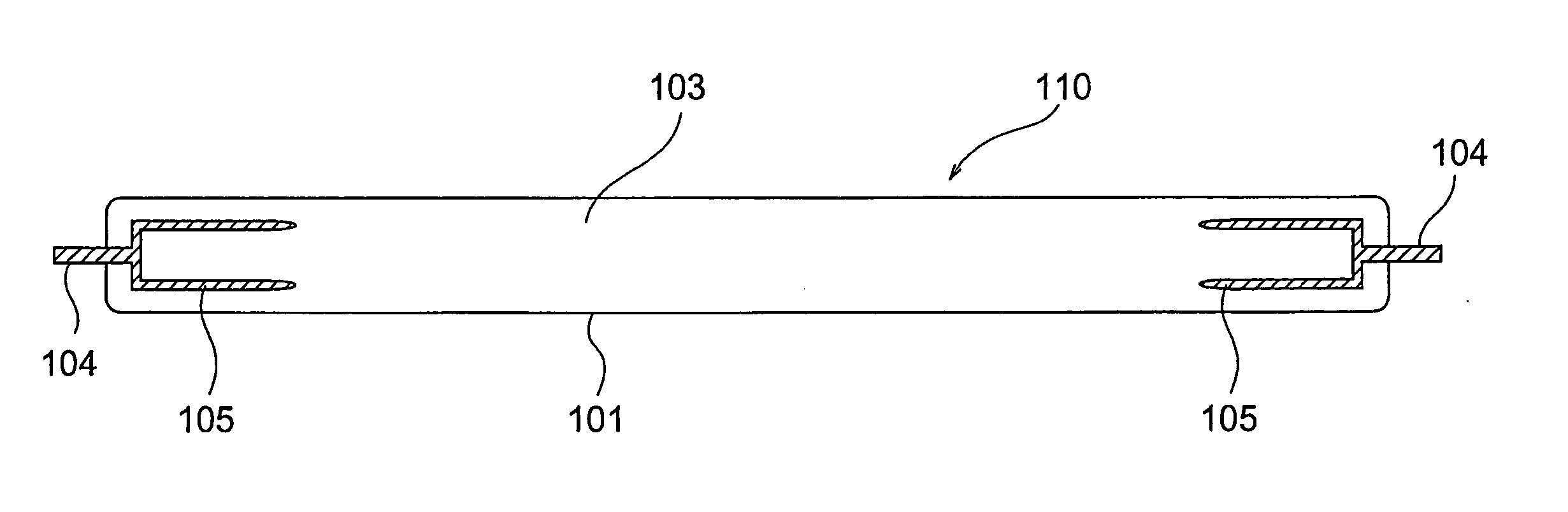
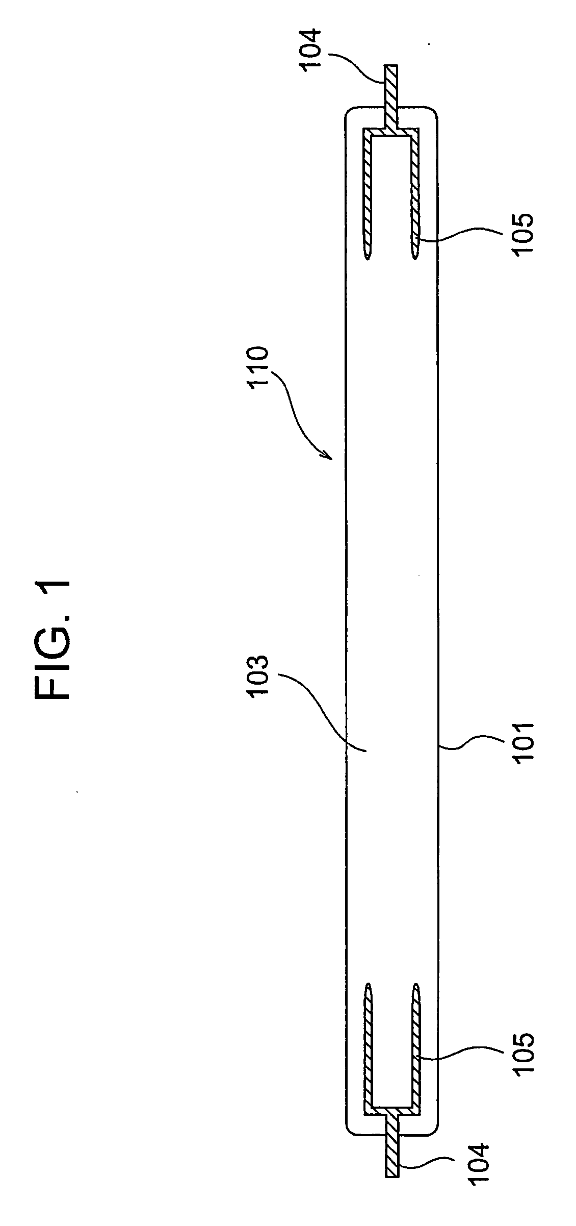
[0045] As shown in FIG. 1, a cold cathode fluorescent lamp 110 according to this invention includes a tube 101, a pair of electron emitting electrodes 105 disposed at both ends of the tube 101 so as to face each other and each having a sectional shape different from that of the electron emitting electrode 102 shown in FIG. 13, and electrode lead wires 104 connected to the electron emitting electrodes 102, respectively. The tube 101 is filled with a filler gas 103.

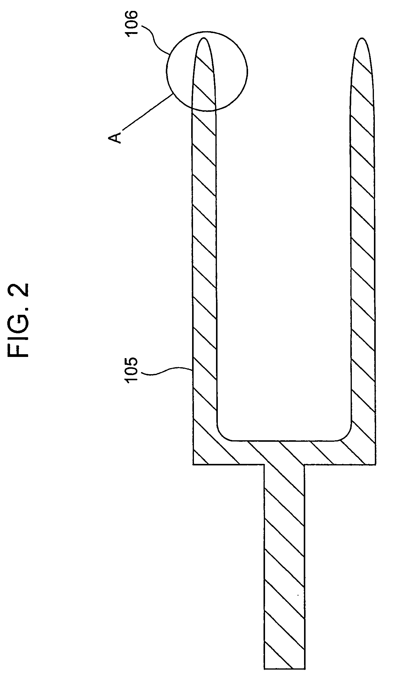
[0046] Specifically, the illustrated tube 101 of the cold cathode fluorescent lamp 110 is made of glass. A material forming the electron emitting electrodes 105 is in the form of tungsten (W) having a high thermal conductivity and containing La2O3 having a small work function. In other words, the illustrated electron emitting electrodes 105 are each formed by a mixture of La2O3 and W. The addition of La2O3 to W is carried out only at a tip portion of ea...


PUM


Abstract

A cold cathode fluorescent tube where an electron emitting electrode is sealed in shows much deterioration in the luminance with time, thereby being not adequate for a long time use. The electrode emitting electrode is formed in such a shape that an electric field is not locally concentrated. By mixing a material of high heat conductivity, such as tungsten, as the material for the electron emitting electrode or using helium of high heat conductivity as the sealing gas, a long life of the cold cathode fluorescent tube is achieved.

Description

TECHNICAL FIELD [0001] This invention relates to a fluorescent lamp and a method of manufacturing the fluorecent lamp and, more specifically, relates to a cold cathode fluorescent lamp having electron emitting electrodes and a method of manufacturing the cold cathode fluorecent lamp. BACKGROUND ART [0002] Generally, cold cathode fluorescent lamps of this type have been widely used in applications of backlights of liquid crystal displays and so on because it has a longer electrode life and is easily miniaturized as compared with a hot cathode fluorescent lamp using a filament. The cold cathode fluorescent lamp comprises, as generally depicted at symbol 100 in FIG. 13, a fluorescent lamp tube 101 in which a phosphor is applied to an inner surface thereof, a pair of opposing electron emitting electrodes 102, and lead wires 104 electrically connected to the electron emitting electrodes 102, respectively. The fluorescent lamp tube 101 is filled with a gas. [0003] The fluorescent lamp tub...

Claims


Application Information

Patent Timeline
IPC IPC(8): H01J61/04H01J61/06H01J9/38H01J9/385H01J9/39H01J61/067H01J61/16
CPCH01J61/0672H01J61/0677H01J61/16H01J61/06H01J61/067H01J9/38H01J9/385
Inventor OHMI, TADAHIROSHIRAI, YASUYUKIMORIMOTO, AKIHIRO
Owner FOUND FOR ADVANCEMENT OF INT SCI
Why Eureka
Try Eureka