
Apparatus for forming a composite structure body

a composite structure and apparatus technology, applied in the field of apparatus for forming composite structures, can solve the problems of low melting point materials, coarse and large particles, and the inability to direct coating nanocomposite materials onto low melting points, so as to achieve the effect of hardly inducing fracture or distortion, low melting points, and degrading structure body formation efficiency

Active Publication Date: 2006-05-18
TOTO LTD +1
View PDF4 Cites 16 Cited by
  • Summary
  • Abstract
  • Description
  • Claims
  • Application Information

AI Technical Summary

Benefits of technology

The present invention is based on the idea of creating new structures by combining different types of brittle materials in a composite structure body. This creates new characteristics that were previously not possible with conventional methods. The microscopic structure of the composite structure bodies formed through this process is significantly different from that of conventionally formed structures. The invention involves the formation of structure bodies on a substrate surface, with the portions of the structure body formed by the crystals of the first brittle material and the crystals or microstructures of the second brittle material. The boundary face between the crystals of the second material is polycrystalline, meaning that the crystals have no crystal orientations and are randomly oriented. The invention also involves the use of a composite structure body with more than one type of brittle material, resulting in the formation of polycrystalline structures with different crystalline orientations. The invention also includes the use of a substrate with a rough surface, which allows for the formation of a dense structure body with high density and high degree of uniformity. The invention provides new ways of creating composite structures with new characteristics, which were previously not possible with conventional methods.

Problems solved by technology

The nanocomposites disclosed in these articles are all obtained by sintering, which induces the grain growth so that the grain size tends to become coarse and large, and accordingly there occurs such a limitation that the sintering does not lead to oxidation.
Additionally, there is involved the heating process, which does not permit the direct coating of nanocomposite materials onto low-melting point materials.
The segregation layer is formed frequently in the grain boundary, and hence there is found a degradation of the freedom in the sense that the crystal particle size control becomes impractical, leading to coarse and large particles in the case where there is large difference in mixing ratio of different powders.
According to this method, however, it is impossible to conduct the nanosize crystal deposition of mixed fine particles of different types in the form of dispersed particles instead of in the form of laminated layers.
In connection with this, a proposal has been made for suppressing the crystal grain growth, but the fact is that there is found some limitation to the types of raw materials to which the proposal is applicable.
More specifically, as for the brittle materials, the structure bodies were able to be formed without using the irradiation of the ion beam, atomic beam, molecular beam, low-temperature plasma, or the like, namely, without using any particular activation procedure, although there was still a problem that the structure bodies were unsatisfactory in the peel strength or partially tended to be peeled off or the density is not uniform, when there were implemented just the fine particle size of 10 nm to 5 μm and bombardment velocity of 3 m / sec to 300 m / sec as specified in the conditions described in the above mentioned patent laid-open.
Thus, they are hard but brittle.
The semiconductors such as silicon, germanium and the like are also brittle materials without ductility.

Method used


Image

  • Apparatus for forming a composite structure body
  • Apparatus for forming a composite structure body
  • Apparatus for forming a composite structure body

Examples


example 1

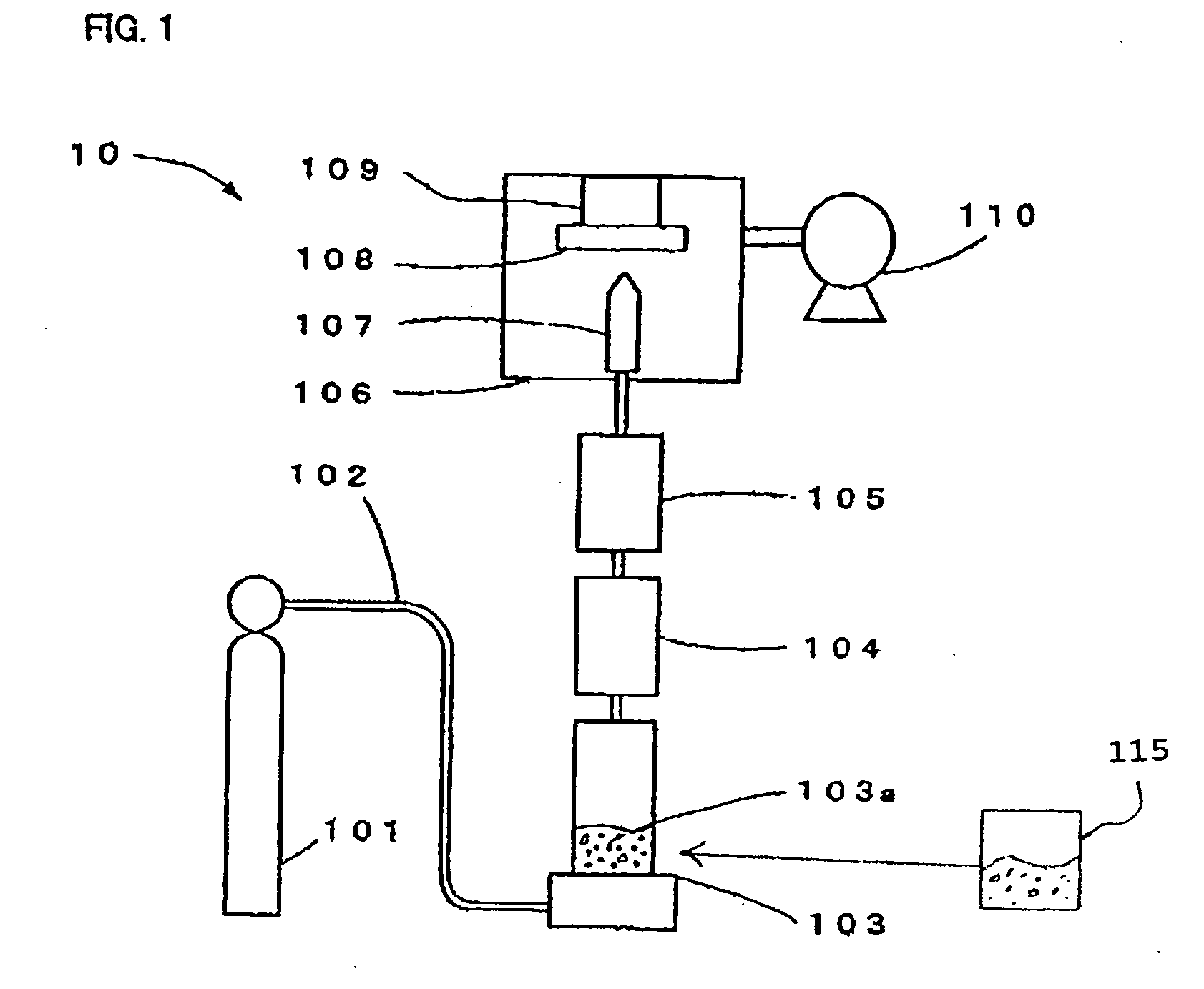
[0093] There was prepared beforehand the mixed powder composed of the aluminum oxide fine particle powder of 0.4 μm in average particle size with the distortion imparted by a planetary mill and the silicon oxide fine particle powder of 0.5 μm in average particle size with the distortion similarly imparted by a planetary mill, and with this powder, a dense composite structure body was formed on an iron substrate by means of the ultra-fine particles beam deposition method, in which structure body the elemental ratio between aluminum and silicon was 75% vs. 25%. The used apparatus corresponded to the one shown in FIG. 1. FIG. 3 shows the structure body surface SEM photograph taken immediately after the formation. FIG. 4 shows the results of the element distribution of aluminum, silicon, and oxygen in this location measured by an EPMA. In these results, the crystallites of 100 nm or less are dispersed independently with no orientation condition, and no solid solution layer composed of a...

example 2

[0094] A composite structure body was formed on a SUS304 substrate at room temperature with the mixed powder composed of aluminum oxide (50 wt %) and lead titanate zirconate (PZT) (50 wt %) by means of the ultra-fine particles beam deposition method in the present invention. FIG. 5 shows the result of the D-E hysteresis measurement of the structure body.

[0095] The measurement specimen was prepared as follows: for the purpose of the D-E characteristic measurement, the surface of the structure body was polished to a thickness of 18 μm on a glass plate with a diamond paste of 1 μm in particle size, the surface was washed and dried, a gold electrode was formed on the upper surface of the structure body in a size of φ5 mm by the vacuum deposition method, and the structure body underwent a heating processing for one hour at 600° C. in the air atmosphere to make the measurement specimen. Incidentally, for the purpose of comparative consideration of the physical properties of the aluminum ...

example 3

[0098] In a manner similar to that in Example 2, a composite structure body was manufactured at room temperature on a SUS 304 substrate with the mixed powder composed of aluminum oxide (80 wt %) and PZT (20 wt %). FIG. 8 shows the transmission electron microscope (TEM) observation image of the obtained structure body. From the EDX element analysis, it has been revealed that in the photograph, the white grain shows the aluminum oxide and the black grain shows the PZT. From these results, it was found that the composite structure body manufactured by the aerosol deposition method, which constitutes the present invention, was formed with the two phases coexisting due to no occurrence of the reaction between aluminum oxide and PZT. Incidentally, the results of the TEM observations revealed that the aluminum oxide fine particles and the PZT fine particles were reduced in particle size in such a way that, in either type of particles, the raw particle size ranged from 0.6 to 0.8 μm at the ...


PUM

PropertyMeasurementUnit
particle sizeaaaaaaaaaa
sizeaaaaaaaaaa
crystallite sizeaaaaaaaaaa

Abstract

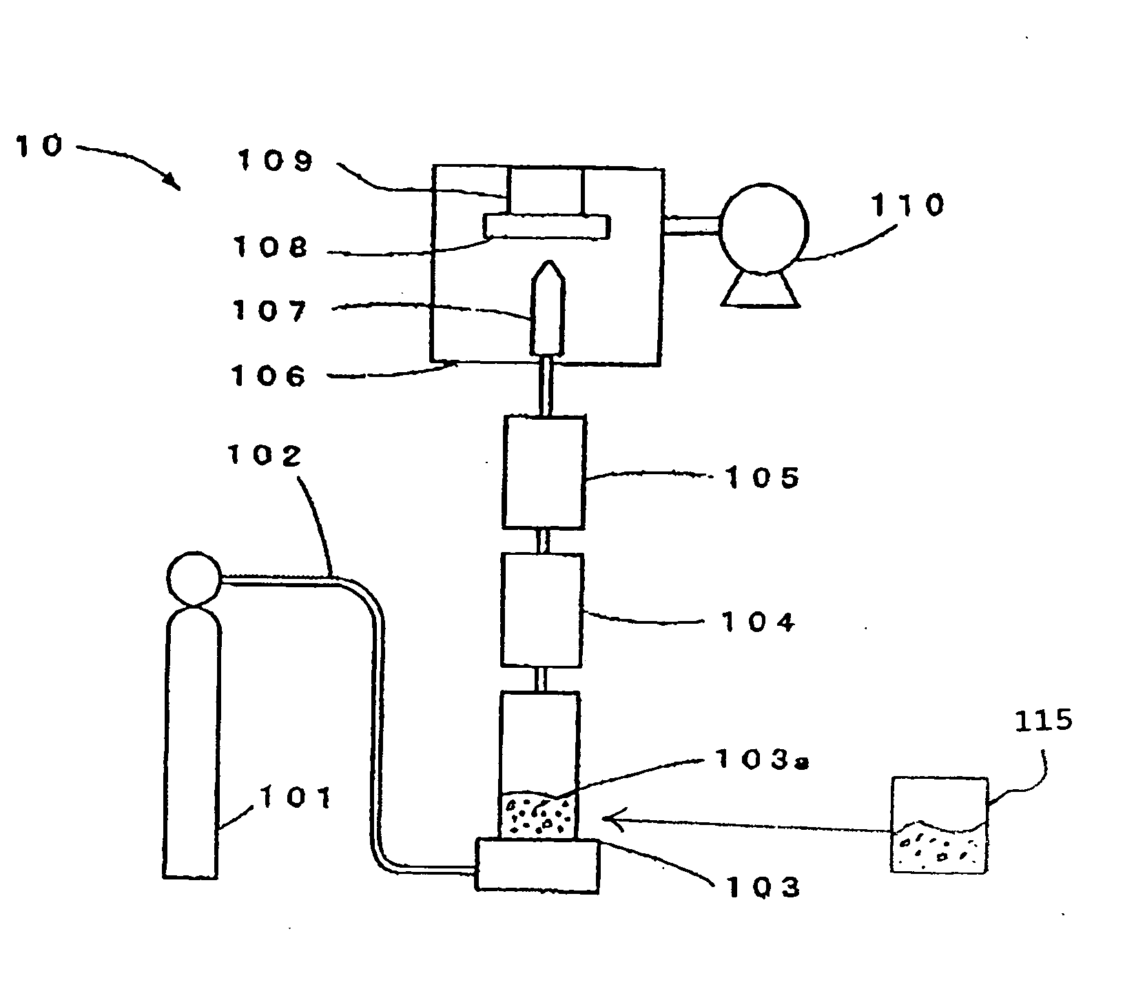
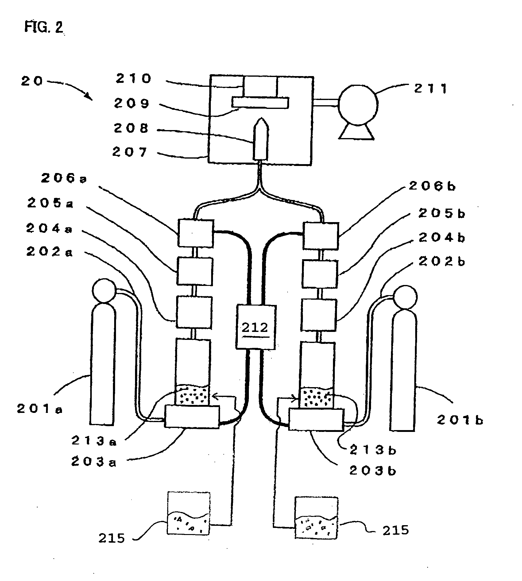
An apparatus for manufacturing a composite structure body is provided which forms structure body having the constitution in which the crystals of more than one type of brittle material are dispersed and having novel properties without involving a heating / sintering process. The apparatus includes an aerosol generator configured to generate an aerosol. The aerosol is generated through dispersing fine particles of more than one type of brittle material, or dispersing composite fine particles, in a gas. The apparatus also includes a nozzle configured to spray the aerosol, a classifier configured to classify the brittle material fine particles in the aerosol, and a disintegrating machine for disintegrating agglomerations of the brittle material fine particles in the aerosol. The composite structure body is manufactured in reduced pressure conditions by bombarding a substrate with the aerosol at a high velocity, whereby at least one of crystals and microstructures of said brittle materials are dispersed.

Description

CROSS-REFERENCE TO RELATED APPLICATIONS [0001] The present invention is a divisional application of co-pending U.S. Patent application Ser. No. 10 / 399,898, which in turn is a 371 (national phase) of PCT International Ser. No. PCT / JP01 / 09305 filed Oct. 23, 2001. The subject matter of these priority documents is incorporated by reference herein.BACKGROUND OF THE INVENTION [0002] 1. Field of the Invention [0003] The present invention relates to a structure body composed of more than one type of brittle material such as ceramics and semiconductors, a composite structure body formed on a substrate from the structure body, and a method and an apparatus for manufacturing thereof. [0004] The structure body and composite structure body involved in the present invention can be applied to, for example, a nanocomposite magnet, a magnetic refrigerator element, an abrasion resistant surface coat, a higher-order structure piezoelectric element composed of a mixture of piezoelectric materials diffe...

Claims


Application Information

Patent Timeline
Patent Type & Authority Applications(United States)
IPC IPC(8): B05C11/00B05C5/00B05B7/00C23C24/04C23C30/00
CPCC23C24/04C23C30/00Y10T428/25Y10T428/265Y10T428/26Y10T428/249967
Inventor HATONO, HIRONORIKIYOHARA, MASAKATSUMORI, KATSUHIKOYOKOYAMA, TATSUROYOSHIDA, ATSUSHIITO, TOMOKAZUAKEDO, JUN
Owner TOTO LTD
Learn More