
Protective coatings

a technology of protective coatings and coatings, applied in the field of protective coatings, can solve the problems of amorphous phases, lower thermal expansion coefficients, and inacceptable coatings for monolithic silicon

Inactive Publication Date: 2006-05-25
UNITED TECH CORP
View PDF7 Cites 73 Cited by
  • Summary
  • Abstract
  • Description
  • Claims
  • Application Information

AI Technical Summary

Benefits of technology

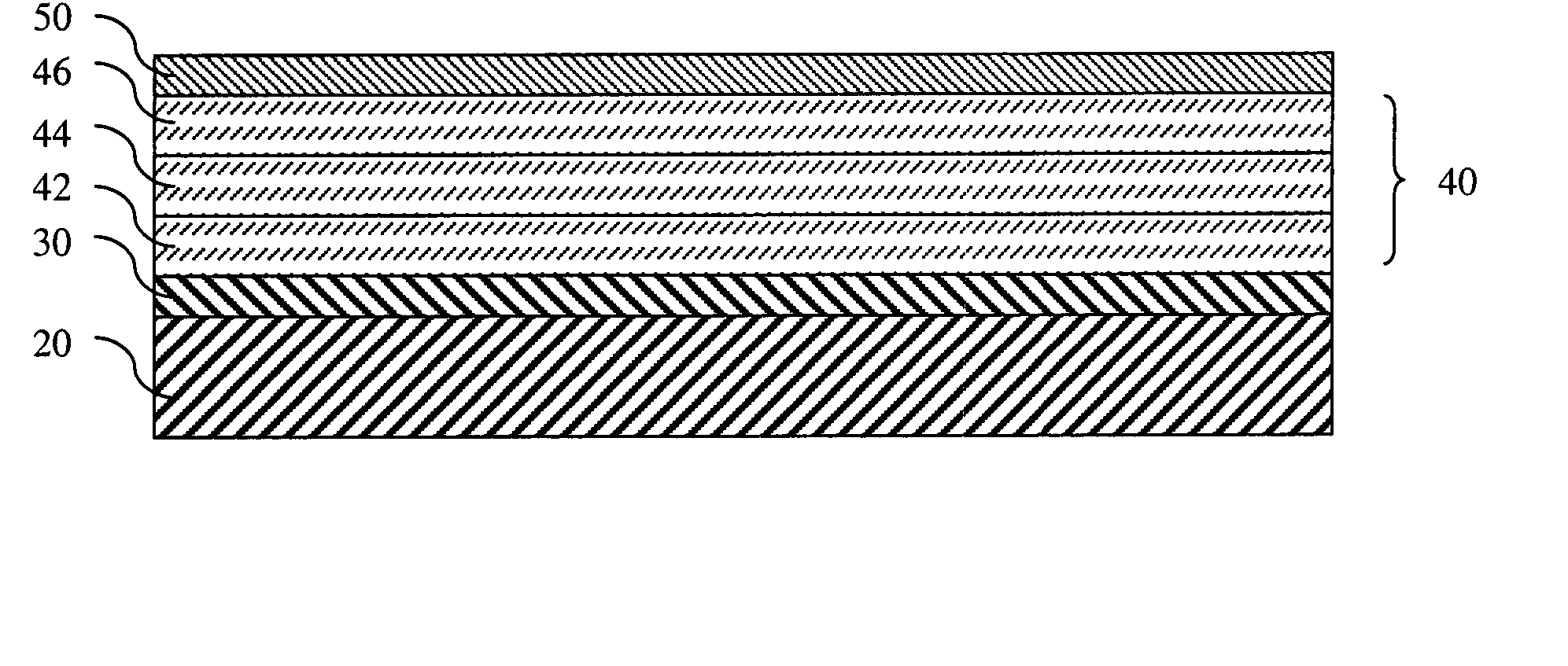
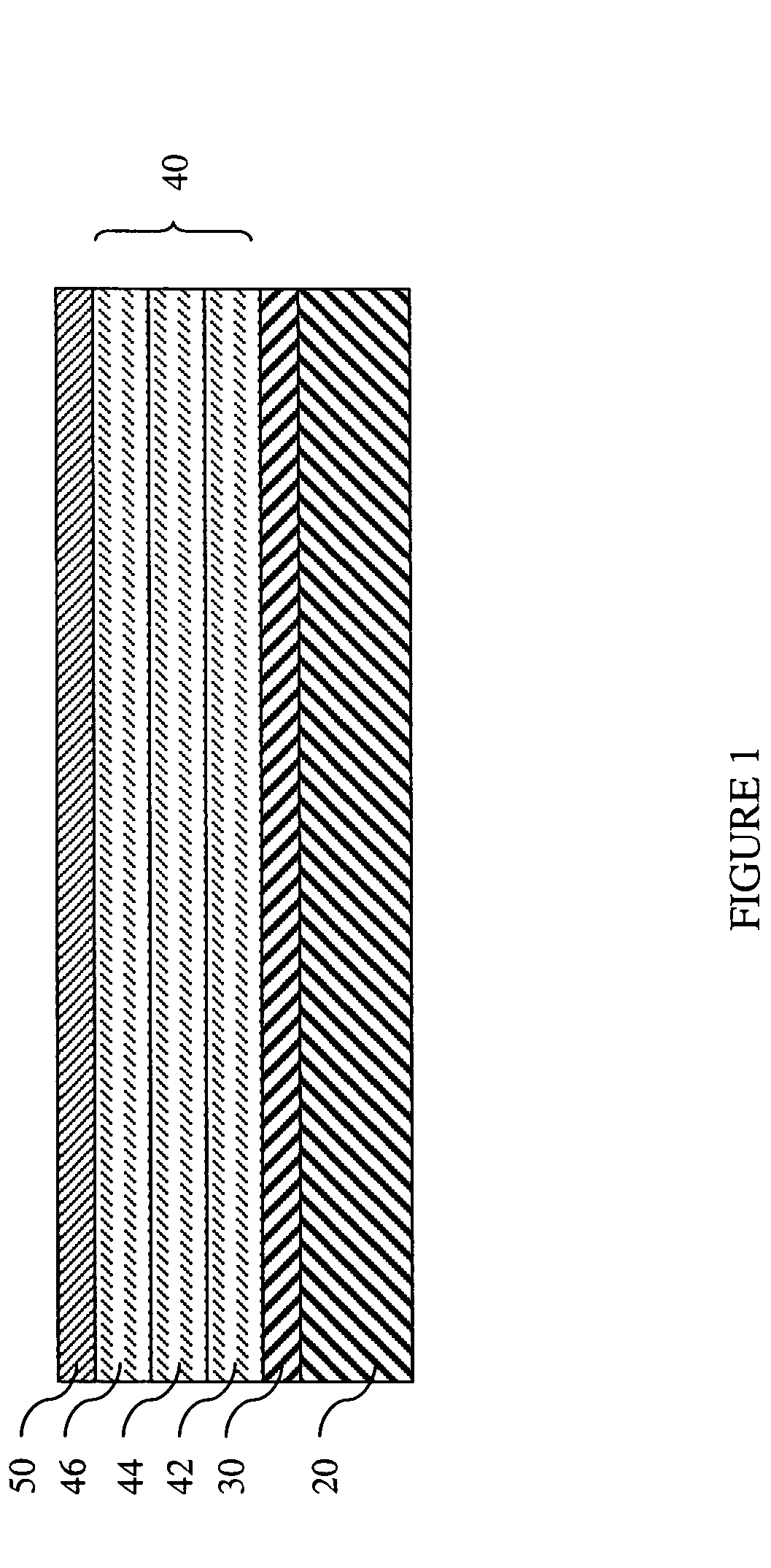
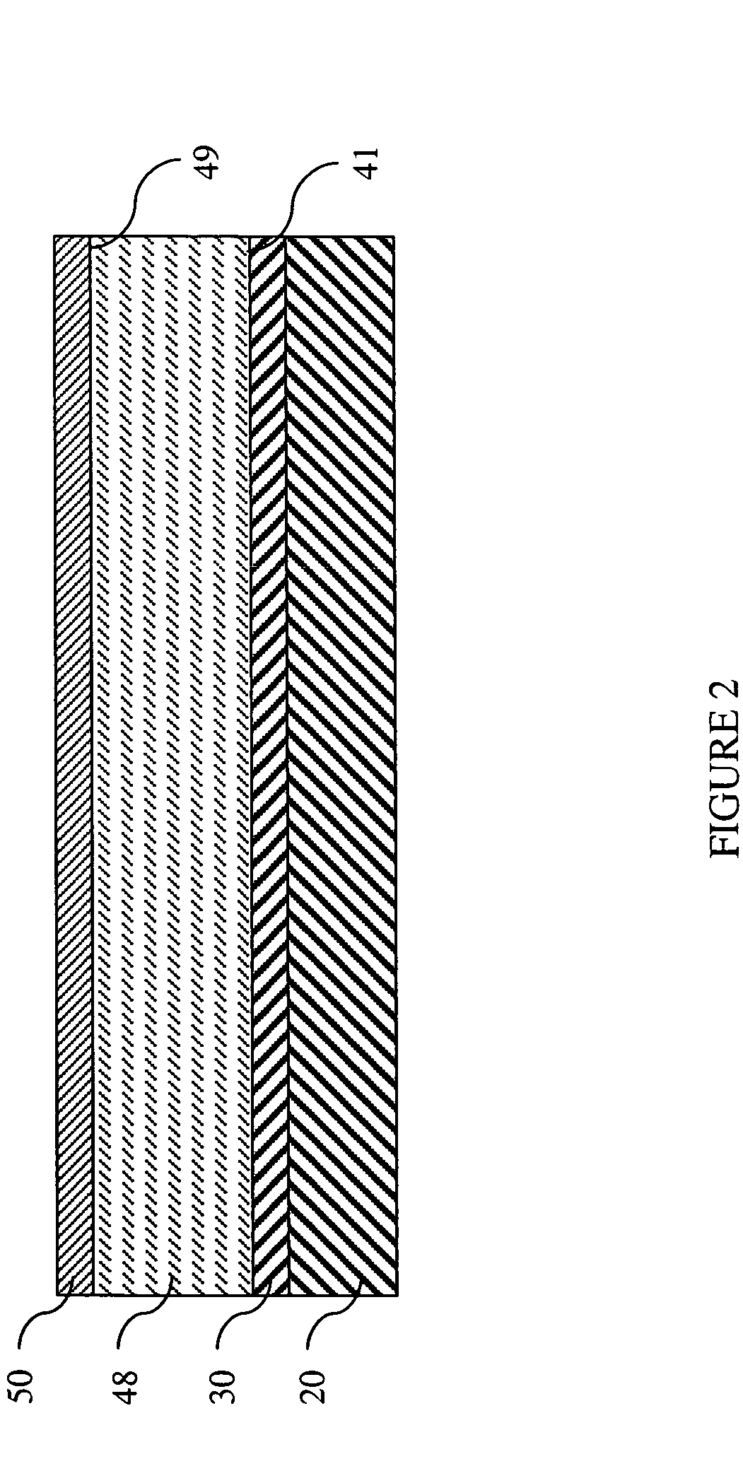
The present invention relates to protective coatings that can be used on various substrates such as silicon-containing substrates having lower coefficients of thermal expansion than silicon carbide. The invention provides adjustable coating chemistry that results in coatings that are appropriate for use on both silicon carbide and silicon nitride substrates. The coatings can be used on various components such as gas turbine engine components. The coating comprises predetermined equilibrium phases that exist in the coating after deposition and can be produced by heat treatment of the coated substrate. The substrate can be silicon nitride or silicon carbide, and the coating can be deposited using thermal spraying or chemical vapor deposition. The technical effects of the invention include improved protection and durability of components in high-temperature environments.

Problems solved by technology

While protective coatings have been developed for use on silicon carbide substrates, these coatings are not acceptable for use on certain monolithic silicon-containing substrates having lower coefficients of thermal expansion than silicon carbide (i.e., silicon nitride).
Furthermore, steam-stable, coefficient of thermal expansion compatible coatings for ceramic substrates often contain complex silicates, and the coating processes used to deposit these coatings on such substrates often result in amorphous phases and / or metastable phases in the coatings that subsequently change to equilibrium phases during or after use.
Such changes may render the coatings unprotective, and therefore, undesirable.

Method used


Image

  • Protective coatings
  • Protective coatings
  • Protective coatings

Examples


example

[0039] In one exemplary embodiment, a suitable yttrium silicate coating was identified for use on a silicon nitride substrate. Silicon nitride has a CTE of about 3.5 ppm / ° C. for room temperature to 1200° C. Since the CTE of yttrium silicate is generally determined by the ratio of yttria and silica present, and by the equilibrium phase content achieved by that ratio of yttria and silica, a yttrium silicate composition having a CTE close to that of the silicon nitride substrate can be selected by referring to FIG. 3, where the effect of the yttria:silica ratio on the CTE of the yttrium silicate composition is shown. For example, as shown in FIG. 3, if a CTE of about 4 ppm / ° C. is desired, a composition comprising about 62-66 mole percent silica (SiO2), or alternatively stated, about 34-38 mole percent yttria (Y2O3), is desirable. The yttria-silica phase diagram shown in FIG. 4 can be used to identify the equilibrium phases of yttria and silica that will be present at a given temperat...


PUM

PropertyMeasurementUnit
thickaaaaaaaaaa
temperatureaaaaaaaaaa

Abstract

Protective coatings are described herein. Embodiments of these coatings comprise substantially only specific equilibrium phases therein, and have a CTE that is substantially equal to the CTE of the substrate upon which the coating is deposited. The desired coatings can be obtained by controlling the application of the coating and / or by heat treating the coated substrate to create the desired phases or microstructure in the coating.

Description

STATEMENT REGARDING FEDERALLY SPONSORED RESEARCH OR DEVELOPMENT [0001] The U.S. Government may have certain rights in this invention pursuant to Contract Number N00014-01-C-0032 with the United States Office of Naval Research.FIELD OF THE INVENTION [0002] The present invention relates generally to protective coatings, especially protective coatings for use on gas turbine engine components. BACKGROUND OF THE INVENTION [0003] Silicon carbide, silicon nitride, and other silica forming ceramics exhibit accelerated oxidation and recession in high temperature aqueous environments such as those found in combustor and turbine sections of gas turbine engines. It is believed that such material recession occurs because SiO2 forming materials react with the water vapor at high temperatures, which leads to volatilization of the silica in the form of Si(OH)x. Accordingly, protective coatings such as environmental barrier coatings (EBCs) may be used on components comprising such materials to slow ...

Claims


Application Information

Patent Timeline
Patent Type & Authority Applications(United States)
IPC IPC(8): B32B13/04B32B9/00B32B19/00
CPCC04B41/009C04B41/5024C04B41/85C04B2111/00405C23C4/105C23C4/18C23C30/00F01D5/288C04B41/4527C04B35/565C04B35/584C04B35/806C04B35/597F05D2230/90F05D2300/611C23C4/11C23C14/22
Inventor EATON, HARRY E.BHATIA, TANIASUN, ELLEN Y.LAWTON, THOMAS H.
Owner UNITED TECH CORP
Learn More