
Electrode structure for lithium secondary battery and secondary battery having such electrode structure

a secondary battery and electrode structure technology, applied in the manufacture of secondary cells, cell components, final product manufacturing, etc., can solve the problems of inability to realize the development of small, lightweight and high-performance secondary batteries is an urgent issue, and the ion battery cannot achieve a secondary battery with a high energy density. , the effect of high capacity and small capacity reduction

Inactive Publication Date: 2006-06-15
CANON KK
View PDF52 Cites 204 Cited by
  • Summary
  • Abstract
  • Description
  • Claims
  • Application Information

AI Technical Summary

Benefits of technology

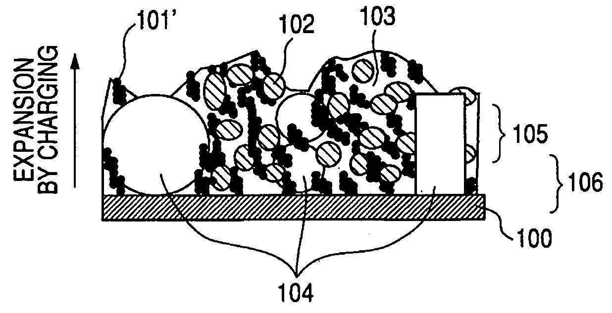
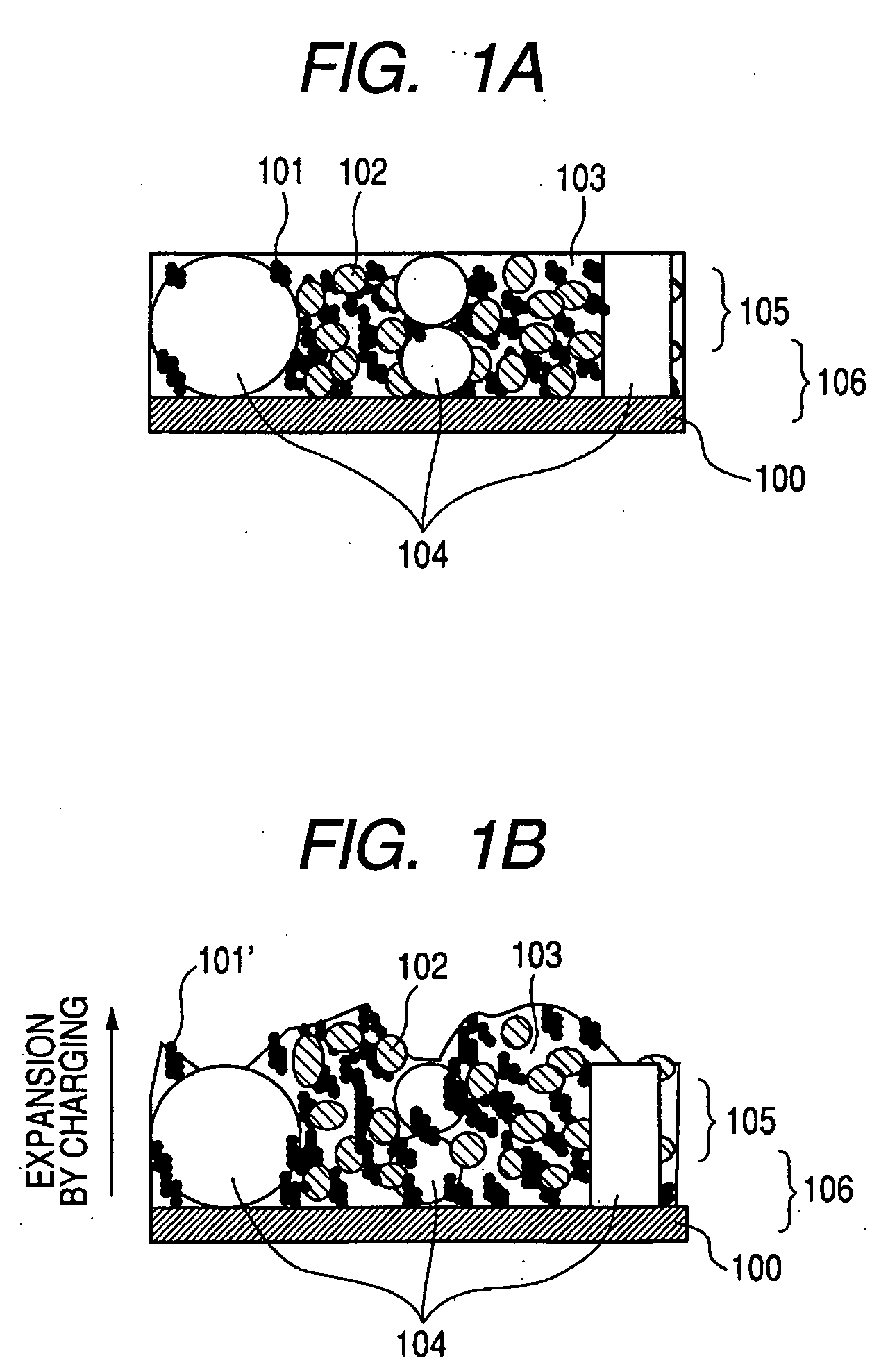
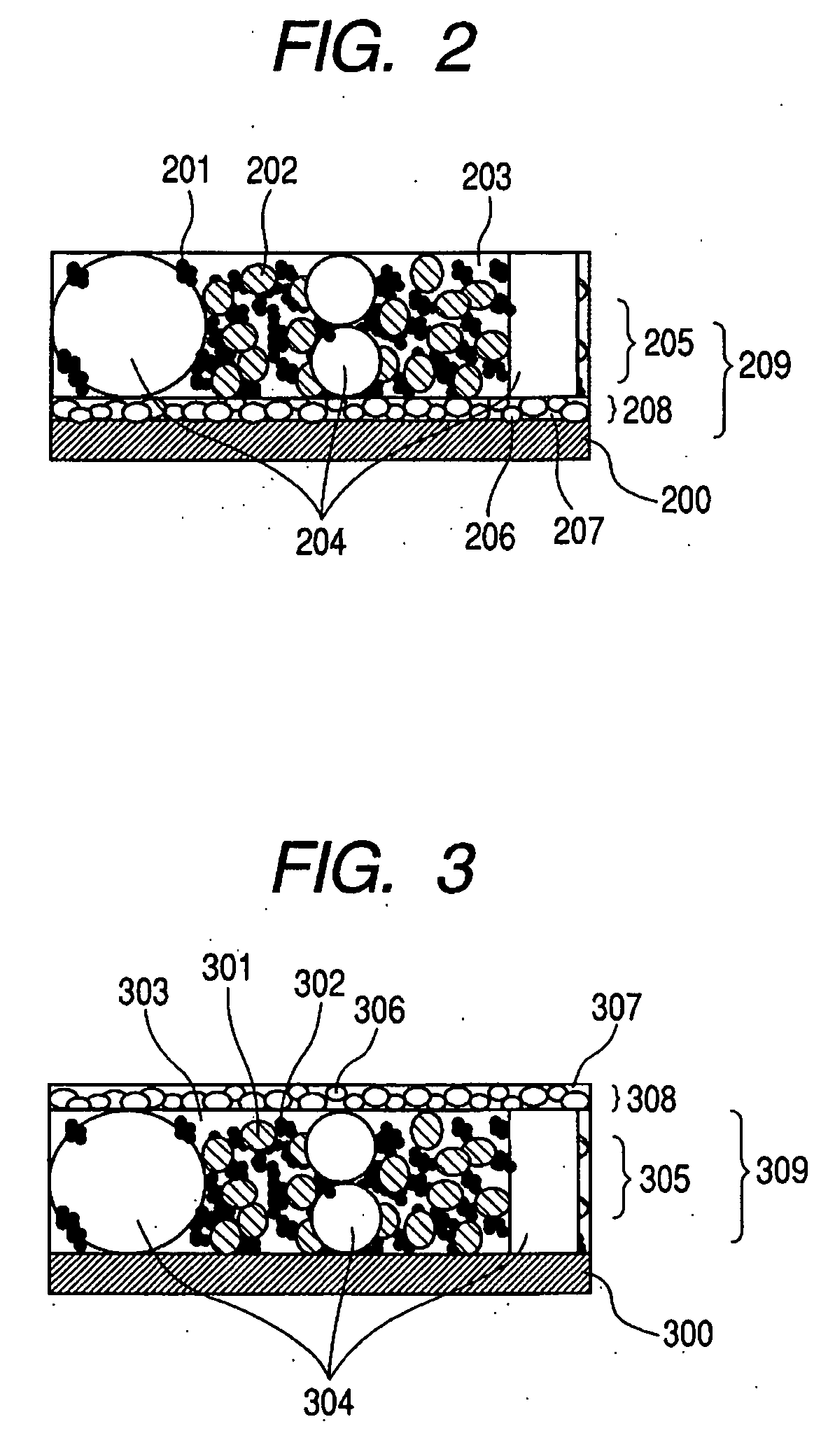
[0014] In view of the above-described points, the object of the present invention is to provide an electrode structure to be used for a lithium secondary battery that shows a small capacity reduction even when the charging / discharging cycle is repeated and has a high capacity and a high energy density, and a lithium secondary battery including such an electrode structure.

Problems solved by technology

Thermoelectric power plants convert the thermal energy obtained by burning fossil fuel into electric energy but it has been made difficult to build new thermoelectric power plants because they give off CO2 gas by a large quantity.
Additionally, development of small, lightweight and high performance secondary batteries is an urgent issue for power source applications in the field of portable appliances such as notebook-sized personal computers, video cameras, digital cameras, batteryular phones and PDAs (personal digital assistants).
However, the above “lithium ion battery” cannot realize a secondary battery with a high energy density that is comparable to a lithium primary battery using metal lithium as a negative electrode material because maximally only ⅙ of a lithium atom per carbon atom can be theoretically intercalated into the negative electrode formed from a carbon material.
Thus, “lithium ion batteries” having a satisfactory cycle life have not been provided if the graphite electrode is made to show a capacity that exceeds the theoretically possible capacity level.
Meanwhile, high capacity lithium secondary batteries having a negative electrode made of metal lithium have been attracting attention as secondary batteries showing a high energy density but have not achieved any commercial success yet because the cycle life of such batteries is short.
There have been proposed techniques to use an alloy of lithium and aluminum for the negative electrode in order to suppress the progress of the reaction between metal lithium and moisture in the electrolyte solution and the organic solvent, which is one of the problems of secondary batteries having a negative electrode made of metal lithium.
However, the lithium alloy is very hard and cannot be wound in a spiral form and hence it is not possible to prepare spiral type cylindrical batteries.
Additionally, the cycle life is not extended as expected and the energy density comparable to a battery having a negative electrode of metal lithium has not been achieved.
Thus, such techniques have not been commercially successful so far for these reasons.
However, the above cited proposal for a lithium secondary battery using such an alloy type negative electrode is accompanied by drawbacks including that the surfaces of silicon particles cannot be coated uniformly by a chemical deposition process involving thermal decomposition and that the thermal decomposition temperature is high and apt to give rise to oxidation of silicon particles.
Therefore, the problem that the internal resistance increases as the charging / discharging cycle is repeated, and consequently the rate of taking out electricity gradually falls is not dissolved sufficiently in comparison with a lithium secondary battery having a graphite electrode.
Although attempts have been made to improve the uneven reaction and make it more uniform by mixing the material of the negative electrode with carbon particles such as graphite particles, the electrochemical reaction relating to the charging / discharging operations of the lithium secondary battery does not take place uniformly in the electrode layer because of the difference of electric storage capacity and volume expansion between metal particles and carbon particles in the case of increasing the amount of lithium that is stored in the negative electrode during charging (metal particles are units of metal powder and carbon particles are units of carbon powder).

Method used


Image

  • Electrode structure for lithium secondary battery and secondary battery having such electrode structure
  • Electrode structure for lithium secondary battery and secondary battery having such electrode structure
  • Electrode structure for lithium secondary battery and secondary battery having such electrode structure

Examples


example 1

(1) Preparation of Main Active Material of Negative Electrode

[0131] Silicon, tin and copper were mixed at an atomic ratio of 82.9:16.6:0.5 (weight ratio of 65:30:5) and molten under an argon gas atmosphere to produce a melt. Subsequently, powder of an Si—Sn—Cu alloy was obtained by means of “Water atomization process” of injecting the melt by highly pressurized water. Then, the obtained powder of the Si—Sn—Cu alloy was crushed in isopropyl alcohol by means of a media mill using a zirconia ball to produce fine powder of the Si—Sn—Cu alloy showing an average particle size of 0.3 μm. Then, graphite powder was added to the obtained fine powder of the Si—Sn—Cu alloy at an amount of 15 wt % and the mixture was crushed in an Attriter mill under an argon gas atmosphere by means of a stainless steel ball for 10 hours to produce fine powder of the Si—Sn—Cu alloy that is compounded with carbon. The obtained Si—Sn—Cu alloy-carbon compounded powder was analyzed by means of an X-ray diffractome...

example 2

[0142] A battery to be evaluated was prepared in the same manner as in Example 1 except that a copper foil having a ten point average height of Rz=2.1 μm and a thickness of 15 μm was used for the current collector of the negative electrode, and the prepared battery was evaluated.

example 3

[0143] The process as described below was used in place of the process of Example 1 to prepare a battery to be evaluated in an evaluation test.

(1) Preparation of Negative Electrode

[0144] A solution obtained by dispersing poly(2-ethylthiophene) at an amount of 10 wt % in a mixed solvent of ethylene carbonate and diethyl carbonate at a volume ratio of 3:7 and adding the obtained mixture to an N-methyl-2-pyrrolidone solution of a polyamide precursor (polyamic acid) such that poly(2-ethylthiophene) was 10 wt % of the solid part of the polyamide precursor (polyamic acid).

[0145] Then, the Si—Sn—Cu alloy-carbon compounded powder as the main active material, artificial graphite powder of pseudo-spherical particles with an average particle size of 22 μm, graphite powder with an average particle size of 5 μm as an auxiliary conductive material, and a solution of N-methyl-2-pyrrolidone as a polyamide precursor (polyamic acid) were mixed such that the weight ratio of the Si—Sn—Cu alloy-carb...


PUM

PropertyMeasurementUnit
Temperatureaaaaaaaaaa
Lengthaaaaaaaaaa
Lengthaaaaaaaaaa

Abstract

In an electrode structure for a lithium secondary battery including: a main active material layer formed from a metal powder selected from silicon, tin and an alloy thereof that can store and discharge and capable of lithium by electrochemical reaction, and a binder of an organic polymer; and a current collector, wherein the main active material layer is formed at least by a powder of a support material for supporting the electron conduction of the main active material layer in addition to the metal powder and the powder of the support material are particles having a spherical, pseudo-spherical or pillar shape with an average particle size of 0.3 to 1.35 times the thickness of the main active material layer. The support material is one or more materials selected from a group consisting of graphite, oxides of transition metals and metals that do not electrochemically form alloy with lithium. Organic polymer compounded with a conductive polymer is used for the binder. There are provided an electrode structure for a lithium secondary battery having a high capacity and a long lifetime, and a lithium secondary battery using the electrode structure and having a high capacity, a high energy density and a long lifetime.

Description

BACKGROUND OF THE INVENTION [0001] 1. Field of the Invention [0002] This invention relates to an electrode material for a lithium secondary battery (lithium rechargeable battery), which is formed from the powder of particles containing a metal such as silicon or tin that forms an alloy with lithium by electrochemical reaction, to an electrode structure including such an electrode material and also to a secondary battery having such an electrode structure. [0003] 2. Related Background Art [0004] The fear for warming the surface of the earth due to the so-called hothouse effect because of the increasing ratio of CO2 gas contained in the atmosphere has been pointed out in recent years. Thermoelectric power plants convert the thermal energy obtained by burning fossil fuel into electric energy but it has been made difficult to build new thermoelectric power plants because they give off CO2 gas by a large quantity. To get rid of this problem, leveling the load of thermoelectric power plan...

Claims


Application Information

Patent Timeline
IPC IPC(8): H01M4/66H01M4/58H01M4/62H01M4/04H01M10/04H01M4/134H01M4/1395H01M4/48H01M4/485H01M4/587
CPCH01M4/134H01M4/1395H01M4/366H01M4/485H01M4/587Y10T29/10H01M4/622H01M4/661Y02E60/122Y10T29/49115H01M4/621Y02E60/10Y02P70/50
Inventor KAWAKAMI, SOICHIROMORITA, AKIRAOGURA, TAKAO
Owner CANON KK
Learn More