Adsorbent, porous filter, air cleaning device, method of cleaning air, and method of manufacturing porous filter

a technology of porous filter and air cleaning device, which is applied in the direction of physical/chemical process catalyst, other chemical processes, separation processes, etc., can solve the problems of high cost, inability to restore fibrous activated carbon, and inability to have satisfactory removal properties

Inactive Publication Date: 2006-06-22
SHARP KK
View PDF9 Cites 21 Cited by
  • Summary
  • Abstract
  • Description
  • Claims
  • Application Information

AI Technical Summary

Benefits of technology

[0028] In addition, “resistant to heat of at least 200° C.” in the present invention means that the porou

Problems solved by technology

Though fibrous activated carbon as an adsorbent used to remove a hazardous chemical substance has an improved adsorption speed as compared to conventional activated carbon, it does not have a satisfactory removal property in a concentration range of the hazardous chemical substance in a ppb order, which is critical for chemical sensitivity.
In addition, since the fibrous activated carbon has an extremely short life of at most one year, it must be replaced frequently.
Furthermore, the fibrous activated carbon cannot be restored and requires a high cost.
In an air cleaning device using the

Method used


Image

  • Adsorbent, porous filter, air cleaning device, method of cleaning air, and method of manufacturing porous filter
  • Adsorbent, porous filter, air cleaning device, method of cleaning air, and method of manufacturing porous filter
  • Adsorbent, porous filter, air cleaning device, method of cleaning air, and method of manufacturing porous filter

Examples


example 1

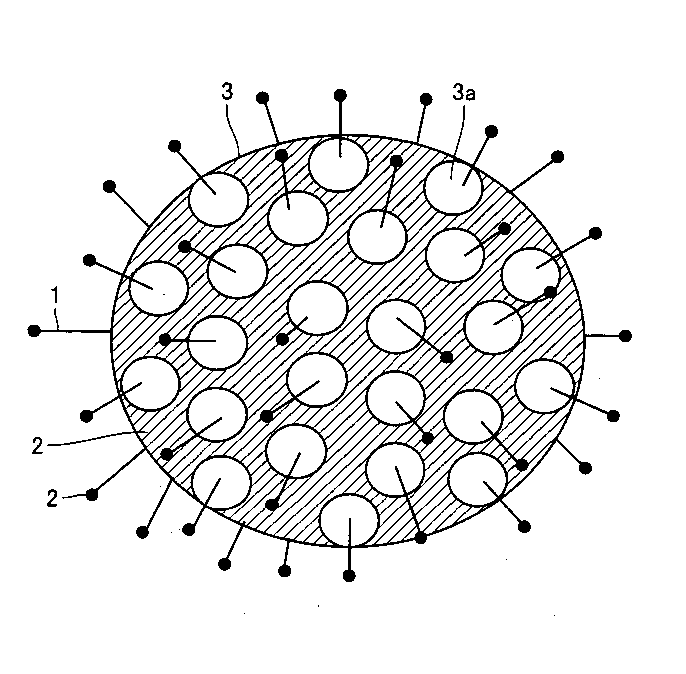
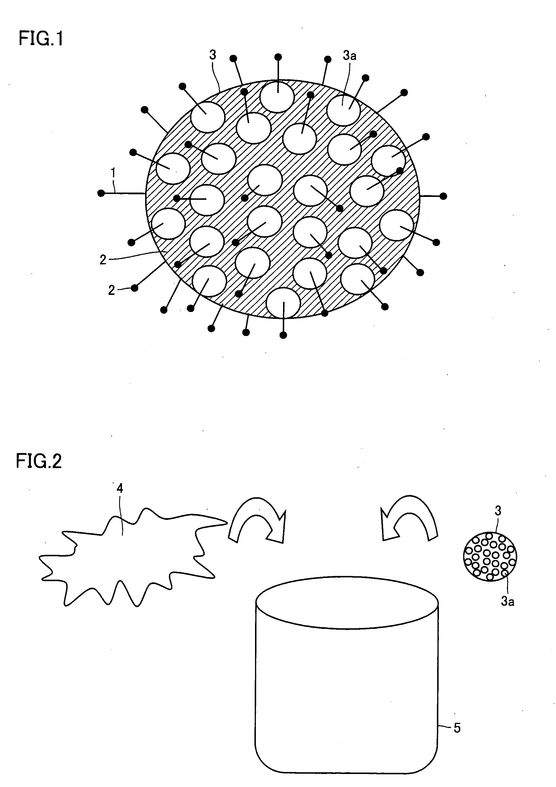
[0071] Diatomaceous earth (produced by Showa Chemical Industry Co., Ltd.) including at least 85 mass % of SiO2 as a main component was used as a porous member. The porous member had a particle diameter of 10 μm, and a plurality of holes formed in the porous member had an average diameter of about 1 m.

[0072] First, a dielectric barrier discharge excimer lamp device enclosing a Xe gas was used to irradiate a surface of the porous member with ultraviolet light having a central wavelength of 146 nm with an irradiance of 10 mW / cm2 for 1 hour to remove a contaminant on the surface of the porous member.

[0073] Then, Ni paste (produced by Nippon Paint Co., Ltd.) including Ni particles having diameters of about 10 nm and the porous member irradiated with ultraviolet light were put in an acetone solvent inside a container, and were agitated by application of ultrasound into the container.

[0074] After agitation, the porous member was removed from the container and placed in a vacuum chamber ...

example 2

[0077] A substrate was formed as follows. On a (111) plane of Si substrate having a silicon oxide film having a thickness of 30 nm formed thereon, an Si thin film having a thickness of 10 nm was formed. Thereafter, Ni thin films as pattern electrodes, each having a square shape of 3 μm per side and a thickness of 100 nm, were formed on both ends of the Si thin film.

[0078] The substrate was then placed in the MPCVD apparatus used in example 1, and a temperature of the substrate was maintained at 800° C. Thereafter, a pressure inside the vacuum chamber was adjusted to about 15 Torr with the pressure control valve, the H2 gas of 80 sccm was introduced through the mass flow controller, and then the microwave of 2.45 GHz (350 W) was introduced to set the H2 gas to a plasma state to clean a surface of the substrate for about 5 minutes.

[0079] Then, the H2 gas of 80 sccm and the CH4 gas of 20 sccm were introduced into the vacuum chamber, the microwave of 2.45 GHz (500 W) was further intro...

example 3

[0082] In a stainless case 16 of an air cleaning device 17 shown in FIG. 7, 0.03 g of the adsorbent of example 1 was housed. Air cleaning device 17 was then intentionally placed in an apparatus of 1 m3 containing diffused toluene of 10 ppm to introduce air inside the apparatus from an air inlet 19 and eject cleaned air from an air outlet 21. A concentration of toluene inside the apparatus was measured at every prescribed time, and a variation in the concentration of toluene over time was evaluated. A result is shown in Table 1. The concentration of toluene inside the apparatus shown in Table 1 was calculated by analyzing composition of gas inside the apparatus using gas chromatography.

TABLE 1Time (min)0510Concentration100.090.001of Toluene InsideApparatus (ppm)

[0083] Considering a fact that the concentration of 10 ppm corresponded to 0.0376 g of toluene, it became apparent from the result shown in Table 1 that about 1.25 g of toluene could be adsorbed per 1 g of the adsorbent of e...


PUM

PropertyMeasurementUnit
Temperatureaaaaaaaaaa
Timeaaaaaaaaaa
Timeaaaaaaaaaa

Abstract

An adsorbent including a porous member having holes and a nanostructure formed on at least a portion of a surface of the porous member, and an air cleaning device including the adsorbent. A porous filter including a porous member having holes and a nanostructure formed on at least a portion of a surface of the porous member, and an air cleaning device including the porous filter. A method of cleaning air for decomposing a hazardous substance using the porous filter and a decomposition gas including a superheated water vapor. A method of manufacturing a porous filter including the steps of growing a nanostructure on at least a portion of a surface of a porous member having holes, allowing a catalyst particle to be contained in a dispersion gas including a superheated water vapor, and spraying the dispersion gas on a surface of the nanostructure to attach the catalyst particle thereto.

Description

[0001] This nonprovisional application is based on Japanese Patent Applications Nos. 2004-367845 and 2004-367846 filed with the Japan Patent Office on Dec. 20, 2004, the entire contents of which are hereby incorporated by reference. BACKGROUND OF THE INVENTION [0002] 1. Field of the Invention [0003] The present invention relates to an adsorbent, a porous filter, an air cleaning device, a method of cleaning air, and a method of manufacturing a porous filter. More specifically, the present invention relates to an adsorbent, a porous filter, an air cleaning device, a method of cleaning air, and a method of manufacturing a porous filter which can efficiently remove hazardous substances. [0004] 2. Description of the Background Art [0005] In addition to a conventional problem of environmental pollution caused by a foul smell, a contaminant or a hazardous chemical substance which is industrially generated from a factory or a clean room, a problem of contamination of air inside a space for ...

Claims


Application Information

Patent Timeline
IPC IPC(8): B01D53/46
CPCA61L9/014A61L9/16B01D53/02B01D53/8603B01D53/8634B01D53/864B01D2253/102B01D2253/308B01D2257/90B01D2257/91B01D2259/4508B01D2259/4566B01J20/20B01J20/205B01J20/28007B01J20/28009B01J20/28014B01J20/28021B01J20/28028B01J20/28097B01J20/3236B01J20/324B01J21/185B01J23/42B01J23/755B82Y30/00B01J20/08B01J20/14B01J20/3204B01J20/3225B01J20/3289B01J20/3295B01J20/0225B01J20/28004B01J20/103
Inventor YAMANAKA, MIKIHIROKUDO, JUNHARA, KEITA
Owner SHARP KK
Why Eureka
Try Eureka