Oxygen concentrator for medical treatment

a technology of oxygen concentrator and oxygen concentrator, which is applied in the direction of respirator, separation process, and dispersed particle separation, can solve the problems of increasing the size of the device, deteriorating the power consumption, etc., and preventing the vibration from propagating to other sites, low failure rate and unfavorable noise level

Inactive Publication Date: 2006-06-29
TEIJIN PHARMA CO LTD
View PDF10 Cites 62 Cited by
  • Summary
  • Abstract
  • Description
  • Claims
  • Application Information

AI Technical Summary

Benefits of technology

[0010] As for the air compressor of the piston system, the contact area of the sealing material is also small, resulting in a small amount of wear particles of the sealing material. For this reason, the failure occurrence rate resulting therefrom is low, while it is disadvantageous in that the noise level is unfavorably high. For this noise, the noise level of the air compressor alone of the class generally used for the foregoing types of the oxygen concentrators falls within a range of 80 to 60 dBA. This is caused by the vibration of the air compressor generated in accordance with the movement of the piston and the low frequency operating sounds entailed by the torque fluctuations of an electric motor. As a means for preventing the vibration from propagating to other sites, there is known a method in which a means for achieving floating by a spring or a rubber vibration isolator as shown in JP-A-63-242901 is taken, and the sounds are enclosed in a dual sound-proof box as shown in JP-A-60-200804, JP-A-59-274654, and the like. However, it is not possible to completely enclose the sounds, and heat generated from the driving electric motor or with air compression caused in the sound-proof box is required to be cooled. Accordingly, the box is equipped with a fan. However, a noise leaks to the outside through the intake port and the exhaust port for the cooling air. For this reason, a bent passage is provided to prevent the noise leakage. Thus, various sound-proof means are taken, resulting in a large size, and large weight device. For a common medical oxygen

Problems solved by technology

This deteriorates the power consumption, and at the s

Method used


Image

  • Oxygen concentrator for medical treatment
  • Oxygen concentrator for medical treatment
  • Oxygen concentrator for medical treatment

Examples


example 1

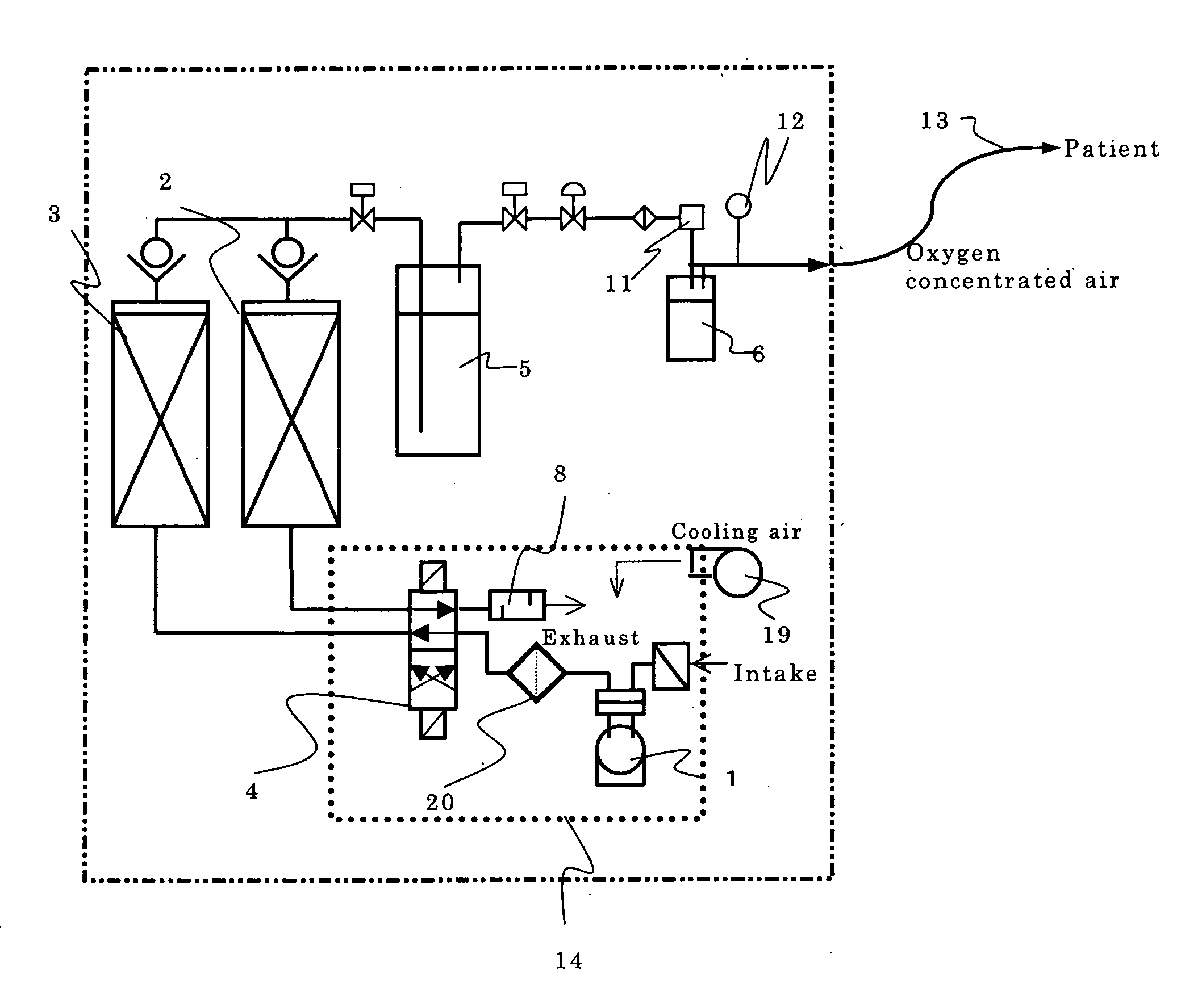
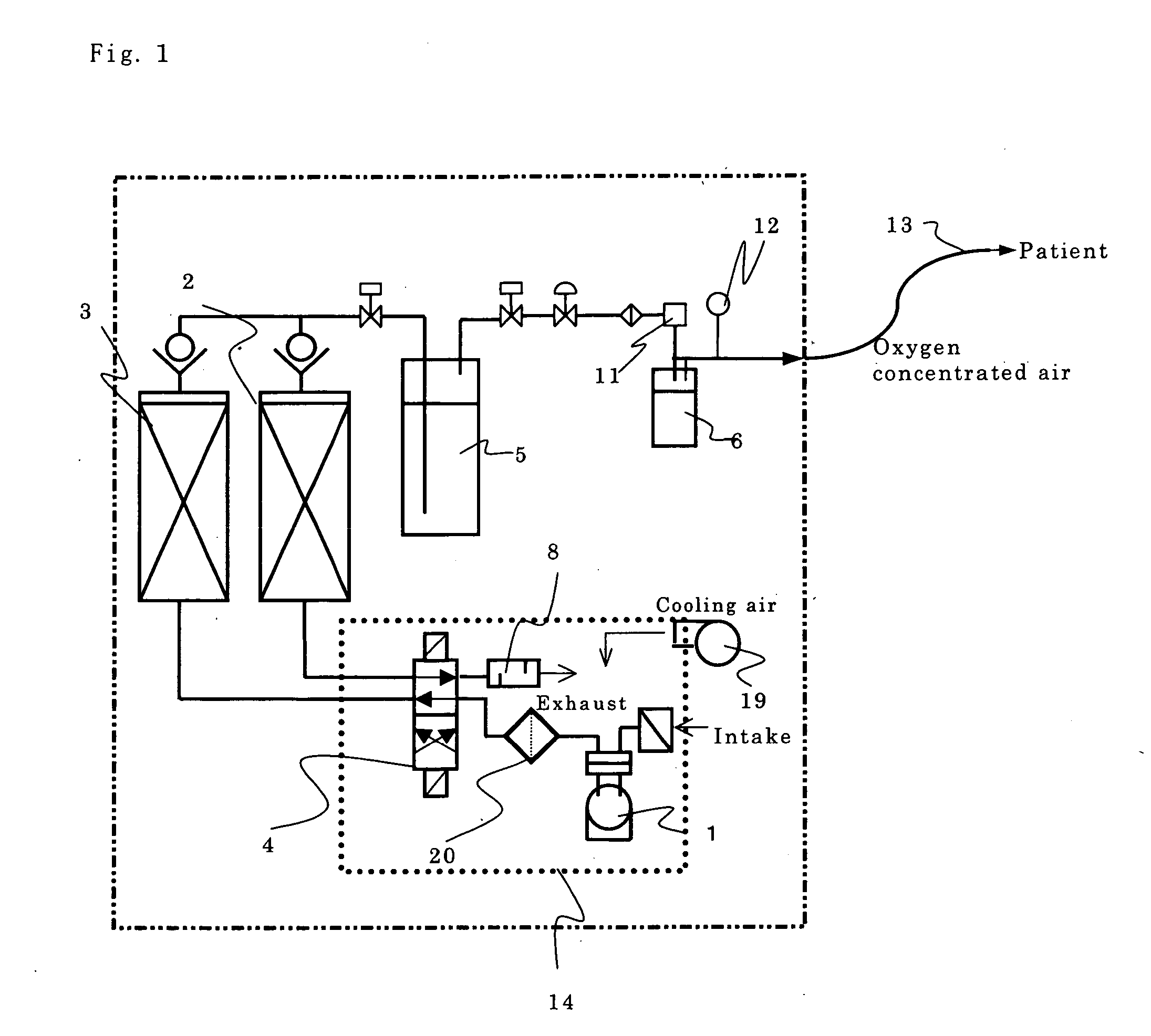
[0036] In an air channel of an oxygen concentrator between two adsorption columns with a diameter of 70 mm and a length of 250 mm, charged with a 5A type sodium zeolite in a density of 0.8, and a helical type compressor (manufactured by TOSHIBA CARRIER Corporation) having a capability of providing a compressed air at a flow rate of 42 L / min when set at a maximum pressure of 120 kPa combined with a DC power-driven brushless electric motor, a filter for collecting the sealing material wear particles, formed of a nonwoven fabric element 23 made of an aromatic polyamide (manufactured by TEIJIN Limited) with an average collection rate of 90% according to the ASHRAE mass method, and having a filtration area of 0.0025 m2 in the cross-sectional area was connected as in the flow sheet of FIG. 1. The number of revolutions was set by an inverter in accordance with the flow rate 3 L / min in terms of the amount of oxygen to be supplied for continuous operation for 5000 hours.

[0037] For such a fi...


PUM

PropertyMeasurementUnit
Fractionaaaaaaaaaa
Speedaaaaaaaaaa
Flow rateaaaaaaaaaa

Abstract

The present invention provides, as a pressure swing adsorption type oxygen concentrator aiming to be used for the home oxygen therapy, and having the device reliability ensuring a low failure occurrence rate, and the adsorption performance stability, ensuring the stable oxygen concentration performance even over a long period, a pressure swing type oxygen concentrator having at least one adsorption column charged with an adsorbent capable of preferentially adsorbing nitrogen rather than oxygen, and an air compressor for pressure supplying and/or vacuum exhausting air to and/or from the adsorption column, characterized by including a nonwoven fabric filter for collecting sealing material wear particles in an air channel between the adsorption column and the air compressor.

Description

TECHNICAL FIELD [0001] The present invention relates to an oxygen concentrator for separating oxygen from air and concentrating it. More particularly, it relates to a pressure swing adsorption type oxygen concentrator particularly used for the oxygen inhalation therapy administered at home for the medical purpose. BACKGROUND ART [0002] A medical oxygen concentrator for use in the home oxygen therapy is used in such a manner that air is used as a raw material, and about 21% oxygen contained therein is concentrated to around 40% to 90%. For the oxygen concentration method, there are a membrane type oxygen concentrator using an oxygen enriching membrane for preferentially transmitting oxygen, and a pressure swing adsorption type oxygen concentrator using an adsorbent for preferentially adsorbing nitrogen rather than oxygen, such as zeolite, and adding air which is a raw material to an adsorption column charged with this, and adsorbing and separating nitrogen. The oxygen concentration a...

Claims


Application Information

Patent Timeline
IPC IPC(8): B01D53/02A61M16/10B01D53/04B01D53/047
CPCA61M16/10B01D53/047B01D2253/108B01D2256/12A61M16/101B01D2259/40003B01D2259/402B01D2259/4533B01D2257/102A61M16/107
Inventor NISHIMURA, KENSHIMAKARI, TAIZOUMOTOKI, TOSHIOKOBAYASHI, HIDEKI
Owner TEIJIN PHARMA CO LTD
Why Eureka
Try Eureka