Heat-resistant film and composite ion-exchange membrane

a technology of composite ion exchange and heat resistance film, which is applied in the direction of fuel cell details, final product manufacturing, chemical/physical processes, etc., can solve the problems of disadvantageous use of expensive devices such as dies and extruders, limited thickness accuracy of the resulting film, and uneven thickness of the resultant film. , to achieve the effect of excellent mechanical strength and ion conductivity, excellent heat resistance, and smoothness and interlaminar peeling resistan

Inactive Publication Date: 2006-06-29
TOYO TOYOBO CO LTD
View PDF9 Cites 34 Cited by
  • Summary
  • Abstract
  • Description
  • Claims
  • Application Information

AI Technical Summary

Benefits of technology

[0024] The present invention solves the problems associated with a prior art described above and provides a film made from a heat-resistant polymer such as polybenzazole, which has a combination of excellent heat resistance, mechanical strength, smoothness and interlaminar peeling resistance, especially a microporous film. The present invention also provides a composite ion-exchange membrane whose mechanical strength and ion conductivity are excellent, especially a polymeric solid electrolyte membrane.

Problems solved by technology

However, such a super engineering plastic has an extremely high melting point and a decomposition temperature which is extremely close to the melting point which make it difficult to use a so called fusion film-forming technology, and a solution film-forming technology is employed generally.
However, any of the production methods described above involves a problem resulting from the use of a die for forming a thin film which is experienced as a difficulty in applying a film-forming solution whose viscosity is departing from an appropriate range as well as a limited accuracy of the thickness of the resulting film.
Moreover, drying and coagulating behaviors are different between the supported side of the thin film and the opposite side since only one side of the thin film subjected to the steps of drying and / or coagulation is supported by a belt or polyester film, resulting in a problematic difference in the characteristics or the structure between the both sides of a resultant film.
Furthermore, the need of expensive devices such as dies and extruders is disadvantageous from an economical point of view.
In addition, such a use of the dies and extruders requires a large amount of a solution or solvent for replacing a resin solution or for washing the devices, which is also disadvantageous from an economical point of view, and also poses a problematic inconvenience in switching the items required for responding a diversity of commercial needs, thus raising a strong desire to develop a production method capable of solving such a problem.
Nevertheless, as described in Chapter 3 in Application of High Temperature Polymers, ed. by Robert R. Luise, CRC Press, 1997, the molecules are aligned in an extruding direction and a draw-down direction, and thus give a problematic film which is readily torn apart when being pulled in the lateral direction.
However, any of these rigid polymers allows, when subjected to a biaxial orientation or an orientation to different directions between the both sides of a film, a molecular chain to readily undergo a so-called intra-plane orientation, resulting in a problematic tendency to undergo interlaminar peeling or brittle destruction in the direction of the film thickness.
While any of the methods described above focused on the characteristics of the sheer viscosity upon processing which is reduced relatively at a high concentration which allows a solution of a rigid polymer to exhibit an optical anisotropy, i.e., liquid crystal property, a film formation using a solution exhibiting an optical anisotropy involves a difficulty in balancing the mechanical properties between the longitudinal direction of the film (MD, direction of film running, machine direction) and the widthwise direction (TD, direction vertical to MD, transverse direction), and also poses a problem of the interlaminar peeling in the direction of the film thickness as described above.
However, in any of the methods described above, a film formed from a liquid crystalline anisotropic solution undergoes the formation of an orientation spot due to the polydomain structure of the liquid crystal phase and tends to be heterogeneous, and still involves a problematically interlaminar peeling in the direction of the film thickness.
Also the problems of the unbalance of the mechanical properties between the longitudinal and widthwise directions are not solved satisfactorily.
However, this method poses a difficulty in obtaining a large amount of films at once by this method, and thus is not preferable from an industrial point or view.
The film forming method using a die described above also involves a problem which is a difficulty in utilizing a processing from a solution at a low concentration a film forming solution because of a too low viscosity, which problem should also be solved.
An aramid film also involves the problems similar to those associated with a polybenzaole film, and is actually industrialized by an extremely complicated process.
A polyamideimide film is also studied in JP-A-7-41559, JP-A-10-226028, JP-A-11-216344, JP-A-2001-151902, JP-A-2002-283369, JP 3183297, JP-A-2001-151910, JP 3196684, JP-A-2000-23339, but a polyamideimide film having excellent thickness accuracy and uniformity has not been obtained at an acceptable cost.
However, the reduction in the film thickness leads to a reduction in the mechanical strength, which may allow the membrane to be readily broken upon adhesion of the polymeric solid electrolyte membrane and an electrode by a hot press, or may result in a problematic deterioration of the electricity generation characteristics due to the peeling of the electrode, once being adhered to the polymeric solid electrolyte membrane, due to the change in the membrane size.
Furthermore, the reduction in the film thickness reduces the fuel permeation preventing ability, resulting in a problematic reduction in the power generation ability or in the fuel utilization efficiency.
However, such a composite polymeric solid electrolyte membrane does not have a sufficient mechanical strength due to the non-continuous structure of the reinforcing material and undergoes a problematic peeling of an electrode due to an inability of suppressing the deformation of the membrane.
JP-A-2000-273214 discloses a method in which a film of a solution of a polybenzazole which is optically anisotropic is formed and then made isotropic by moisture absorption followed by coagulation whereby obtaining a polybenzazole film, but a polybenzazole film obtained by the described method is a transparent and highly dense film, which is not suitable for the purpose of impregnating it with an ion-exchange resin to give an ion-exchange membrane.
However, when using a polybenzazole solution whose polymer concentration is 1% by weight or higher, the polybenzazole solution becomes highly viscose, resulting in a formation of streaks in the direction of a squeegee, which leads to a difficulty in obtaining a smooth film.
Accordingly, a poor economical performance and insufficient strength and elasticity of the resultant film are experienced unfortunately.
When such a asymmetrically structured polybenzazole support film is impregnated with an ion-exchange resin, a sufficient impregnation with the ion-exchange resin is not achieved at the region where the dense structure is formed, resulting in a problematically insufficient electricity generating ability of a resultant ion-exchange membrane.

Method used


Image

  • Heat-resistant film and composite ion-exchange membrane
  • Heat-resistant film and composite ion-exchange membrane
  • Heat-resistant film and composite ion-exchange membrane

Examples


example a1

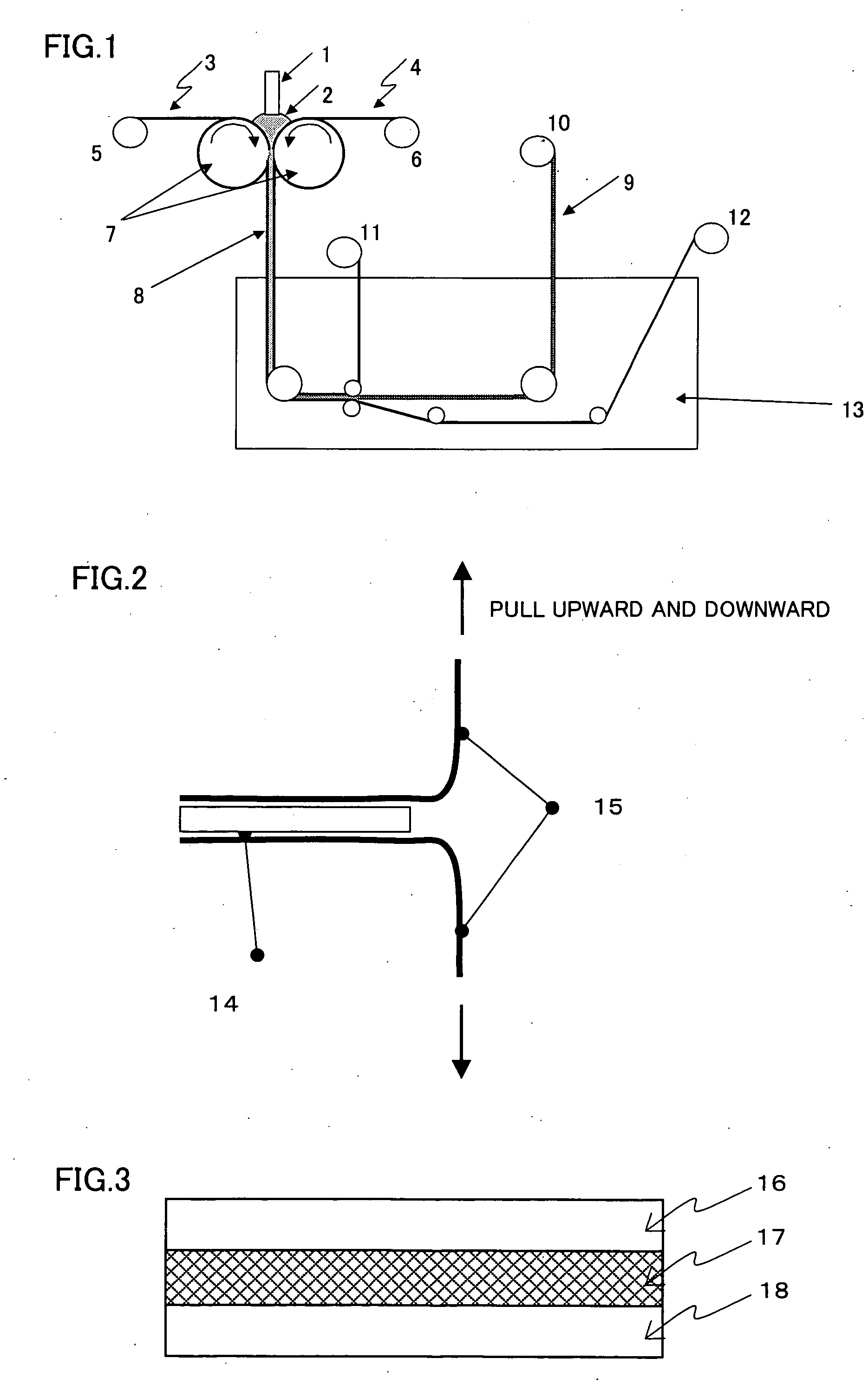
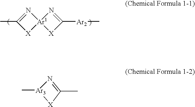
[0124] A solution containing 14% by weight of a polyphenylene cisbenzobisoxazole polymer of IV=24 dl / g in polyphosphoric acid was diluted with methanesulfonic acid to form an isotropic solution whose polyparaphenylene cisbenzobisoxazole concentration was 2.5% by weight. This solution was passed through a filter purported to have a pore size of 20 μm, and then sandwiched between two porous supports made from a polypropylene provided between two counter rolls, which were then rotated in opposite directions to roll the solution while feeding the solution together with the polypropylene porous supports, and then coagulated for 30 minutes in atmosphere of the chamber kept constantly at 25° C. and 80% relative humidity, and then introduced into a coagulation bath. The coagulation solution was water at 60° C. During the step described above, the gap between the counter rolls was adjusted so that the solution thickness became 200 μm. In the coagulation bath, the polypropylene porous support...

example a2

[0128] A solution containing 14% by weight of a polyparaphenylene cisbenzobisoxazole polymer of IV=24 dl / g in polyphosphoric acid was diluted with methanesulfonic acid to form an isotropic solution whose polyparaphenylene cisbenzobisoxazole concentration was 2.5% by weight. This solution was passed through a filter purported to have a pore size of 20 μm, and then sandwiched between two porous film supports made from a polypropylene provided between two counter rolls, which were then rotated in opposite directions to roll the solution while feeding the solution together with the polypropylene porous supports, and then coagulated for 30 minutes in atmosphere of the chamber kept constantly at 25° C. and 80% relative humidity, and then introduced into a coagulation bath. The coagulation solution was water at 60° C. During the step described above, the gap between the counter rolls was adjusted so that the solution thickness became 200 μm. In the coagulation bath, the polypropylene porou...

example b1

[0134] A 3% by weight solution of a polyparaphenylene terephthalamide resin whose logarithmic viscosity was 6 in 100% sulfuric acid was passed through a filter purported to have a pore size of 20 μm, and then sandwiched between two porous supports made from a polypropylene provided between two counter rolls, which were then rotated in opposite directions to roll a dope while feeding together with the polypropylene porous supports, and then introduced into a coagulation bath. The coagulation solution was 30% sulfuric acid at 25° C. During the step described above, the gap between the counter rolls was adjusted so that the solution thickness became constant. In the coagulation bath, the polypropylene porous supports were peeled off and the resin solution thin later was brought into contact with the coagulation solution to effect a further coagulation. A schematic view of the production method is shown in FIG. 1. Thereafter, the resin film thus formed was washed with warm water at 50° ...


PUM

PropertyMeasurementUnit
thicknessaaaaaaaaaa
pore sizeaaaaaaaaaa
temperatureaaaaaaaaaa

Abstract

The present invention is a heat-resistant film comprising at least any one of a polybenzazole, aramid and polyamideimide produced by introducing a thin film made by a roll, slit or press from a polymer solution sandwiched between at least two supports into a coagulating bath and peeling the supports off in the coagulating bath to effect the coagulation, and a composite ion-exchange membrane having a surface layer consisting of an ion-exchange resin excluding a porous film on the both side of a composite layer formed by impregnating said film with the ion-exchange resin. A heat-resistant film having a combination of excellent heat resistance, mechanical strength, smoothness and interlaminar peeling resistance, especially a microporous heat-resistant film, and a composite ion-exchange membrane employing the same which has an excellent ion conductivity are provided.

Description

TECHNICAL FIELD [0001] The present invention relates to a film made from a heat-resistant polymer such as polybenzazole, which has a combination of excellent heat resistance, mechanical strength, smoothness and interlaminar peeling resistance, especially a microporous film. The present invention also relates to a composite ion-exchange membrane whose mechanical strength and ion conductivity are excellent, especially a polymeric solid electrolyte membrane. BACKGROUND ART [0002] Recently, a rapid advancement in IT field poses also to a non-porous or porous film employed as a part of its related electronic instrument or cells a severe commercial requirement with regard to heat resistance, chemical resistance, size stability, thickness accuracy, uniformity and price in response to the requirement for a higher performance or a smaller size of such an instrument or cell. [0003] For example, a super engineering plastic such as polybenzazole, polyimide, aramid and the like is excellent in t...

Claims


Application Information

Patent Timeline
Patent Type & Authority Applications(United States)
IPC IPC(8): B01D71/06B01D67/00B01D69/12B01D71/56B01D71/62B01D71/64B29C41/24B29D7/01C08J5/18C08J9/26H01B1/12H01M8/02H01M8/10
CPCB01D67/0013B01D67/0016B01D69/12B01D71/56B01D71/62B01D71/64B29C41/24B29D7/01B29K2077/10B29K2079/00B29K2079/085B29K2105/0079C08J5/18C08J9/26C08J2379/04H01B1/122H01M8/0291H01M8/1027H01M8/103H01M8/1081H01M2300/0082H01M2300/0094Y02E60/521B01D2323/46B01D2325/22B01D2325/24B01D2325/42H01M8/0289Y02E60/50Y10T428/249953Y02P70/50B29C39/18
Inventor OKAMOTO, KAZUTAKEKOBAYASHI, HISATOKAWAHARA, KEIZOHAMAMOTO, SHIROTAKASE, SATOSHISAKAGUCHI, YOSHIMITSUINUKAI, CYUJIYAMADA, JUNSAKURA, DAISUKENAKAMURA, MUNEATSU
Owner TOYO TOYOBO CO LTD
Why Eureka
Try Eureka