Ion sensors formed with coatings

a technology of ion sensors and coatings, applied in the field of ion sensing, can solve the problems of unsteady heat release of burning fuel, reduced possibility of localized fuel rich areas, and reduced possibility of premixing, so as to reduce thermal stress on the mechanical connection

Inactive Publication Date: 2006-07-27
WOODWARD GOVERNOR CO
View PDF19 Cites 7 Cited by
  • Summary
  • Abstract
  • Description
  • Claims
  • Application Information

AI Technical Summary

Benefits of technology

[0012] In an alternate embodiment, the coating system layers (i.e., the dielectric coating layer and the electrode layer) are extended up the nozzle center body such that the mechanical connection to the wire is made further from the flame, thereby reducing thermal stress on the mechanical connection.

Problems solved by technology

The premixing also decreases the possibility of localized fuel rich areas where carbon monoxides and unburnt hydrocarbons are not fully oxidized.
Unfortunately, many of these systems have experienced problems associated with instabilities and flashback.
Combustion instability can occur when the air / fuel ratio is too lean and the flame becomes unstable and creates pressure fluctuations, resulting in unsteady heat release of the burning fuel that can produce destructive pressure oscillations or acoustic oscillations.
When flashback occurs in the fuel nozzle, the temperatures inside the nozzle rise above the design temperature for the nozzle material causing costly damage, which can include fragments of the nozzle material, usually metal, tending to pass through the turbine system usually causing severe damage to the turbine blades.
This type of failure, regardless of frequency, can be catastrophic in terms of down time, maintenance costs and lost revenue.
Another challenge facing both industrial and aircraft turbines in the detection of the flame and a phenomenon known as lean blow-off.
This construction technique limits the application of ion sensing due to the hardware complexity and space constraints required for the ion-sensing apparatus.
Additionally, the mechanical fasteners carry the risk of losing preload over repeated thermal cycles, thereby allowing sensor components to fail and potentially causing downstream damage due to debris entering turbine blades or other exhaust system components.

Method used


Image

  • Ion sensors formed with coatings
  • Ion sensors formed with coatings
  • Ion sensors formed with coatings

Examples


Embodiment Construction

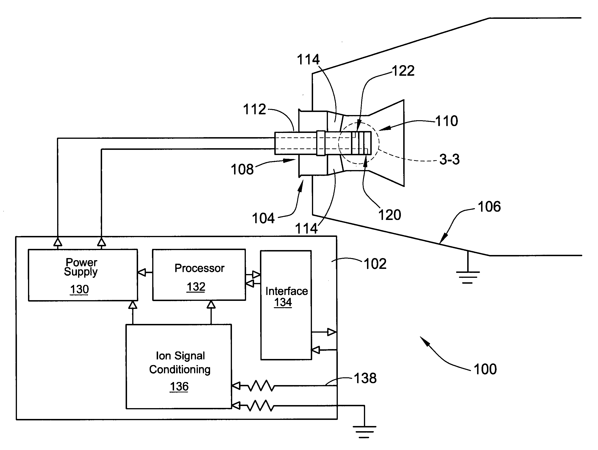
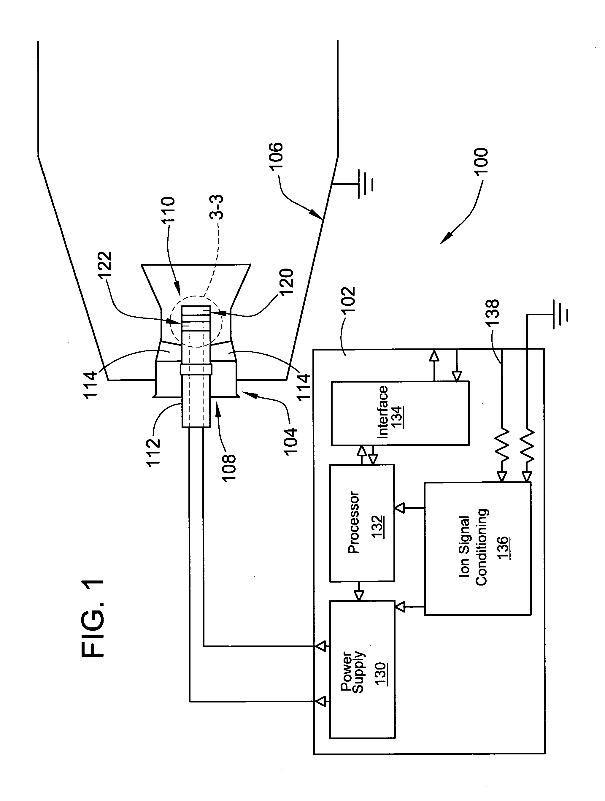
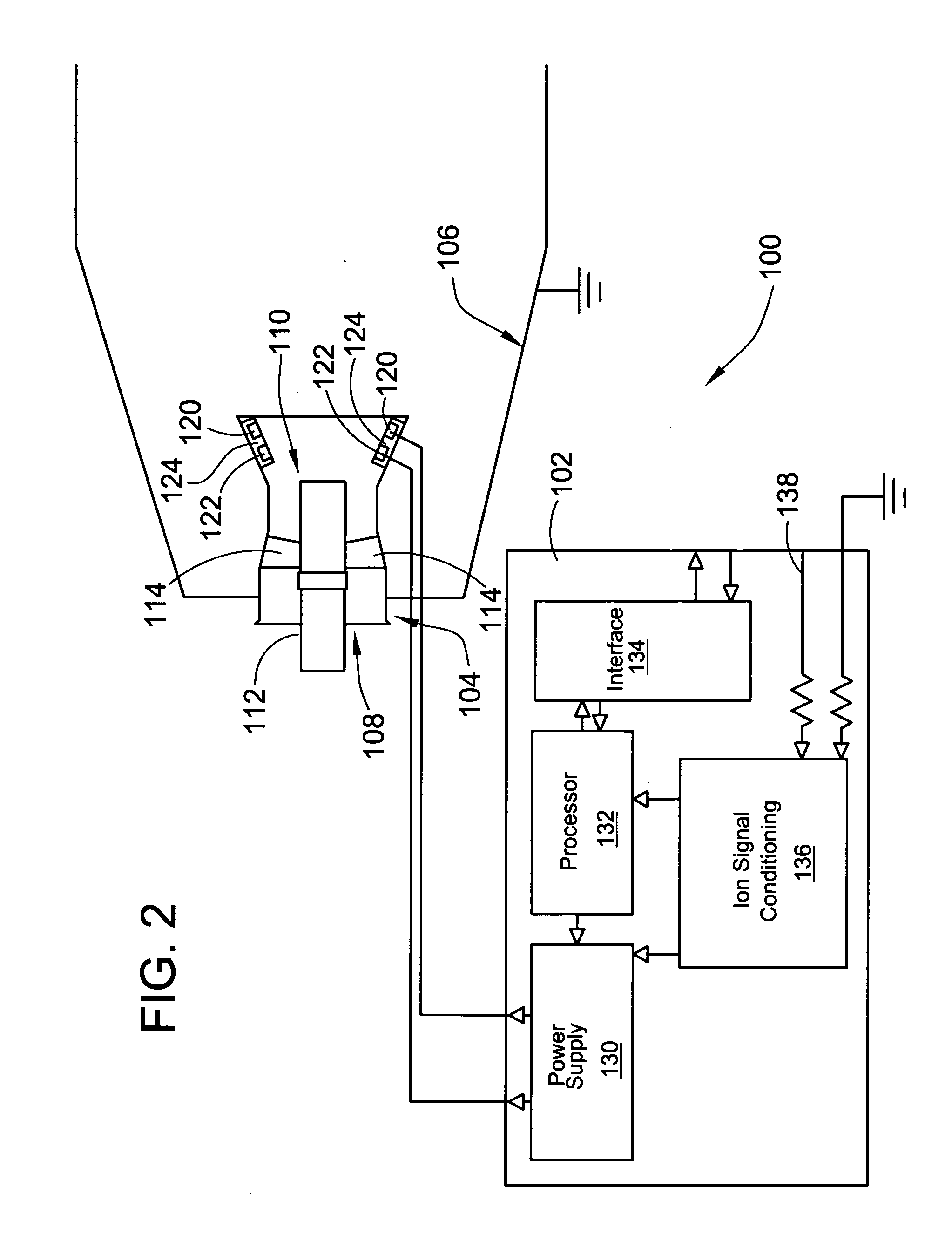
[0020] The present invention provides an apparatus to sense ion current in a combustion region of a continuous combustion system such as a gas turbine, industrial burner, industrial boiler, or afterburner utilizing ionization signals. The invention may be used with any hydrocarbon fuels, such as liquid or gaseous fuels, that produce free ions in the flame when the fuel is burned. The magnitude of the free ions in the flame is proportional to the concentration of hydrocarbons, and therefore the measured ion current is also proportional to the magnitude of free ions. The invention eliminates many of the mechanical components comprising the sensing elements of prior designs where the mechanical components are retained to the mounting structure by mechanical fasteners and over repeated thermal stress cycles and mechanical vibration, the mechanical components can become loose, thereby exposing the turbine or engine to downstream damage from flying debris. The dielectric coating layer of ...


PUM

PropertyMeasurementUnit
temperaturesaaaaaaaaaa
conductiveaaaaaaaaaa
surface areaaaaaaaaaaa

Abstract

The invention provides an ion sensor for use in a fuel nozzle of a gas turbine combustor and other combustor surfaces that uses thin-film coatings to form both the dielectric and electrode layer of the ion sensor and methods to provide an electrical connection to the electrode layer. The dielectric layer electrically insulates the sensor from the combustor surface, which is typically grounded. The electrode layer, typically a metallic material capable of withstanding high temperatures in the combustion environment without delamination from the dielectric layer, is applied over the dielectric layer and forms the ion-sensing electrode. A wire protrudes through the dielectric layer to connect to the electrode layer and provides for the ion-sensing electrode to be controlled outside of the combustion zone (e.g., to a control module for signal processing).

Description

FIELD OF THE INVENTION [0001] This invention pertains to ion sensing, and more particularly to ion sensors for continuous combustion systems. BACKGROUND OF THE INVENTION [0002] Continuous combustion systems such as gas turbine engines are used in a variety of industries. These industries include transportation, electric power generation, aircraft engines and afterburner applications, and process industries. During operation, the continuous combustion system produces energy by combusting fuels such as propane, natural gas, diesel, kerosene, or jet fuel. One of the byproducts of the combustion process is emission of pollutants into the atmosphere. The levels of pollutant emissions are regulated by government agencies. Despite significant reductions in the quantity of environmentally harmful gases emitted into the atmosphere, emission levels of gases such as NOx, CO, CO2 and hydrocarbon (HC) are regulated by the government to increasingly lower levels and in an ever increasing number o...

Claims


Application Information

Patent Timeline
Patent Type & Authority Applications(United States)
IPC IPC(8): G01N27/62
CPCG01N27/626F23N1/005F23R3/286F23N2241/20B29C33/04B29C33/38
Inventor BENSON, KELLY J.VANDYNE, EDRILEY, PATRICK
Owner WOODWARD GOVERNOR CO
Why Eureka
Try Eureka