Method and apparatus for determining a property of a fluid which flows through a biological tubular structure with variable numerical aperture

a biological tubular structure and numerical aperture technology, applied in the field of optical spectroscopy, can solve the problems of considerable time required for transport and analysis, and achieve the effects of high numerical aperture, high numerical aperture, and increased signal-to-noise ratio

Inactive Publication Date: 2006-08-17
KONINKLIJKE PHILIPS ELECTRONICS NV
View PDF7 Cites 56 Cited by
  • Summary
  • Abstract
  • Description
  • Claims
  • Application Information

AI Technical Summary

Benefits of technology

[0015] In accordance with a further preferred embodiment of the invention the high numerical aperture for the optical spectroscopy is above 0.6, preferably above 0.8. This way a large proportion of the return radiation from the detection volume is collected which increases the signal to noise ratio. A second advantage of a high numerical aperture is a small detection volume that fits completely in a blood vessel.
[0016] In accordance with a further preferred embodiment of the invention a movement of the biological tubular structure during the analysis is tracked. This enables to move the detection volume together with a move of the biological tubular structure. This way measurement errors due to a movement of the patient can be avoided. In particular this eliminates errors which can be caused by breathing or other unintentional movements of the patient. The tracking of the movement of the biological tubular structure is performed by optical detection of the movement using a high numerical aperture for precise tracking of the movement. Especially the accuracy in the z-direction strongly depends on the size of the NA.

Problems solved by technology

The transport and the analysis take a considerable amount of time, varying between two days and typically 20 minutes in emergency situations.

Method used


Image

  • Method and apparatus for determining a property of a fluid which flows through a biological tubular structure with variable numerical aperture
  • Method and apparatus for determining a property of a fluid which flows through a biological tubular structure with variable numerical aperture
  • Method and apparatus for determining a property of a fluid which flows through a biological tubular structure with variable numerical aperture

Examples


Embodiment Construction

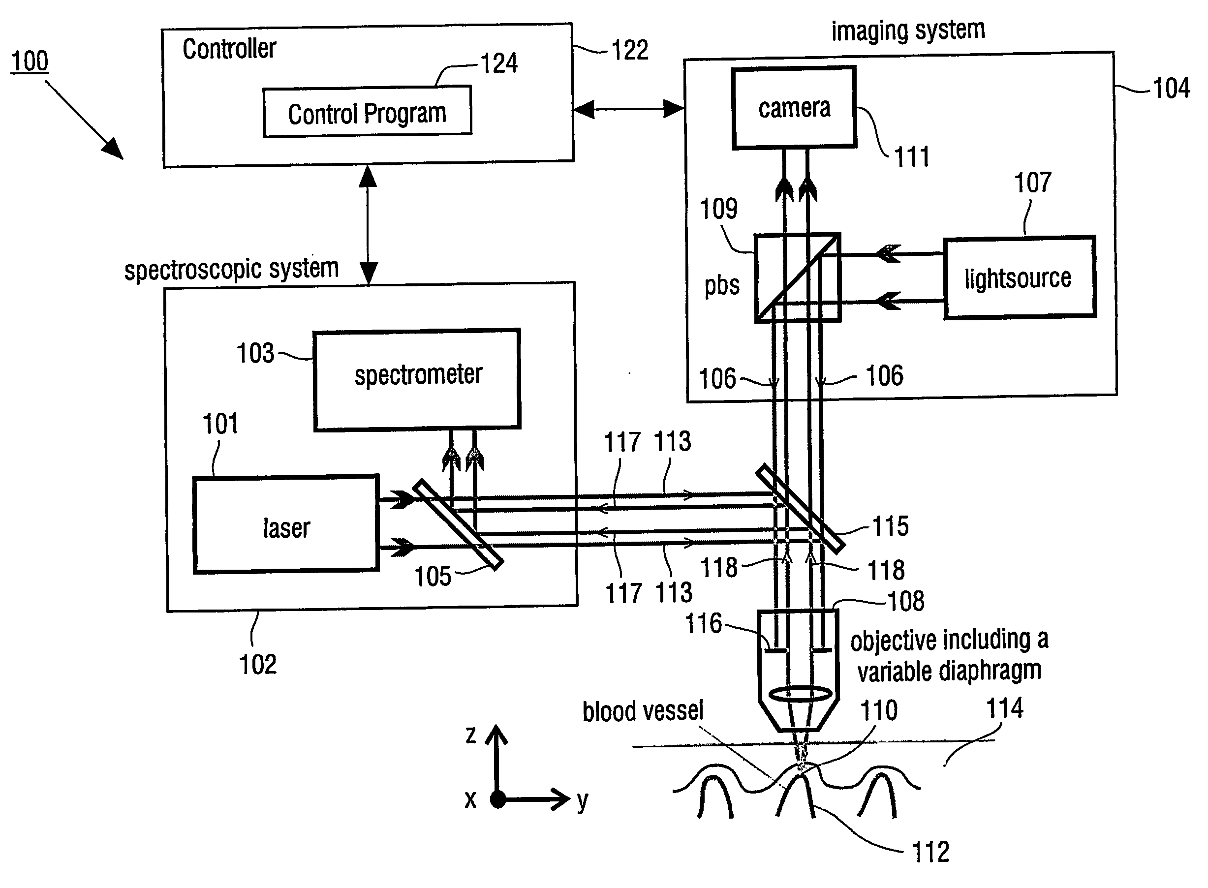
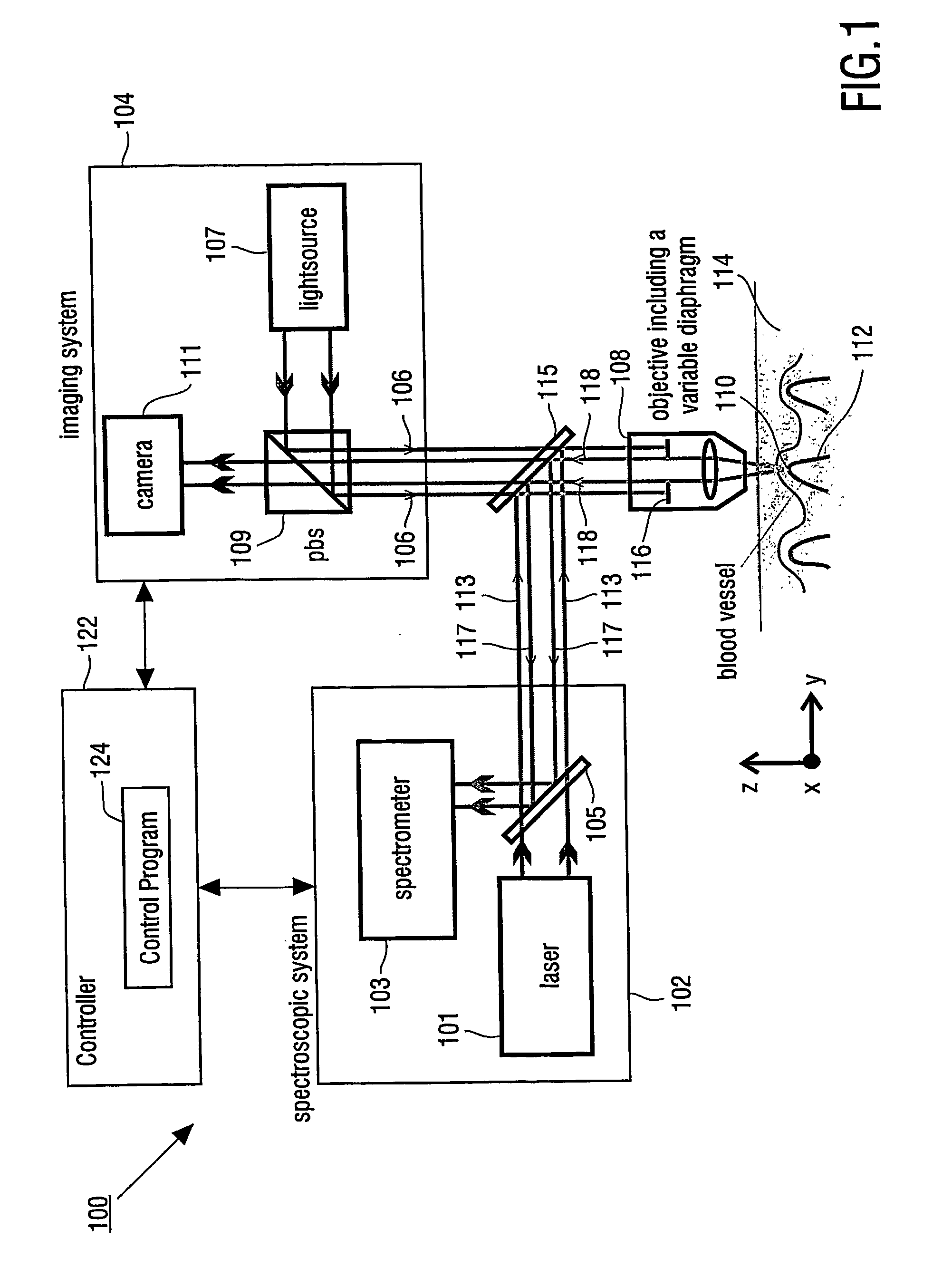
[0026]FIG. 1 shows a block diagram of an apparatus which can be used for determining a property of a fluid which flows through a biological tubular structure, such as blood flowing through a capillary vessel under the skin of a patient. Apparatus 100 has Raman spectroscopic system 102 for confocal Raman spectroscopy and imaging system 104.

[0027] Raman spectroscopic system 102 has laser light source 101 and spectrometer 103. Raman return radiation is directed to spectrometer 103 by mirror 105 of spectroscopic system 102.

[0028] Imaging system 104 has light source 107, which provides an incident light beam 106, which is directed through objective 108 to detection volume 110, which is located within blood vessel 112 in skin 114 of a patient's body. Objective 108 has variable diaphragm 116, which enables to control the numerical aperture of objective 108.

[0029] Further imaging system 104 has polarizing beam splitter 109 and CCD camera 111.

[0030] Incident light beam 106 of light sourc...


PUM

PropertyMeasurementUnit
timeaaaaaaaaaa
depthsaaaaaaaaaa
diameteraaaaaaaaaa

Abstract

The present invention provides for an apparatus and a method for determining a property of a fluid which flows through a biological tubular structure, such as blood flowing through a capillary vessel (112) under the skin (114). This enables in vivo non-invasive blood analysis. An objective (108) having a variable numerical aperture (116) is used to enable automatic detection of a blood vessel (112) and to provide a high signal to noise ratio of the return radiation for the purposes of the spectroscopic analysis and to provide a small detection volume that fits completely within the target region.

Description

FIELD OF THE INVENTION [0001] The present invention relates to the field of optical spectroscopy, and more particularly to the usage of optical spectroscopic techniques for analytical purposes. BACKGROUND AND PRIOR ART [0002] Usage of optical spectroscopic techniques for analytical purposes is as such known from the prior art. WO 02 / 057759 A1 shows a spectroscopic analysis apparatus for in vivo non-invasive spectroscopic analysis of the composition of blood flowing through a capillary vessel of a patient. The capillary vessel is imaged by a monitoring system and an excitation beam is directed to the capillary vessel in order to perform the spectroscopic analysis. For example near-infrared radiation is used for excitation of Raman scattering. The Raman scattered radiation is spectroscopically analysed for determination of blood properties. [0003] The in vivo analysis of blood has a number of advantages as compared to prior art blood analysis, where blood is drawn from the arm, for ex...

Claims


Application Information

Patent Timeline
Patent Type & Authority Applications(United States)
IPC IPC(8): G02B5/08G02B7/195A61B5/00G01N21/47G01N21/64G01N21/65
CPCA61B5/0059A61B5/489G01N21/4795G01N21/64G01N21/65G01N2021/653G01N2021/655A61B5/0068
Inventor VAN BEEK, MICHAEL CORNELISHORSTEN, JAN BAPTIST ADRIANUS MARIAVAN DER VOORT, MARJOLEINLUCASSEN, GERHARDUS WILHELMUSCASPERS, PETER JACOBUS
Owner KONINKLIJKE PHILIPS ELECTRONICS NV
Why Eureka
Try Eureka