Austempering/marquenching powder metal parts

a technology of metal parts and marquenching powder, which is applied in the field of austempering/marquenching powder metal parts, can solve the problems of reducing bending fatigue strength, limited use, and lowering wear resistance, and achieves the effect of high performance powder and medium to high density

Inactive Publication Date: 2006-08-17
BORGWARNER INC
View PDF17 Cites 13 Cited by
  • Summary
  • Abstract
  • Description
  • Claims
  • Application Information

AI Technical Summary

Benefits of technology

[0012] A powder metal part is made by compaction at room temperature or an elevated temperature followed by sintering, a secondary densification, heat treating, and optional secondary operations. The particulate materials preferably include iron, 0-2.0 wt % copper, 0.15-0.9 wt % carbon, 0.5-2.0 wt % molybdenum, 0.5-4.5 wt % nickel, 0-4.0 wt % chromium, and 0-1.5 wt % silicon. At least one secondary densification is applied to the part after compaction and pre-sinter / sinters steps to achieve medium to high density. The secondary densification is part of a double press double sinter (DPDS) or is a mechanical working depending on the application requirements. The powder metal is heat treated by austempering or marquenching followed by tempering. A unique composite microstructure is achieved from austempering by controlling the powder chemistry and the holding time at an elevated temperature. The combination of a secondary densification and austempering or marquenching produces a high performance powder metal part for demanding applications.

Problems solved by technology

Powder metal parts may be used in a variety of applications, but have found only limited use in high-performance applications, such as within an automobile transmission, due to the fact that many powder metal parts suffer from reduced bending fatigue strength and lowered wear resistance.

Method used


Image

  • Austempering/marquenching powder metal parts
  • Austempering/marquenching powder metal parts
  • Austempering/marquenching powder metal parts

Examples


first embodiment

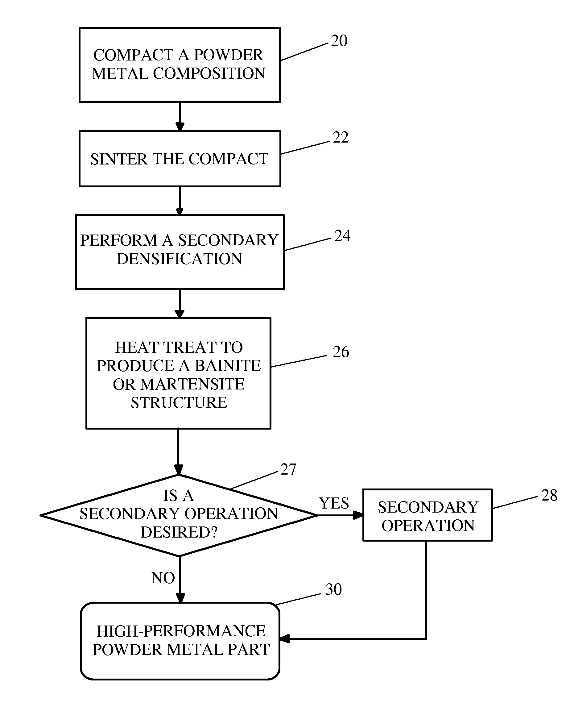
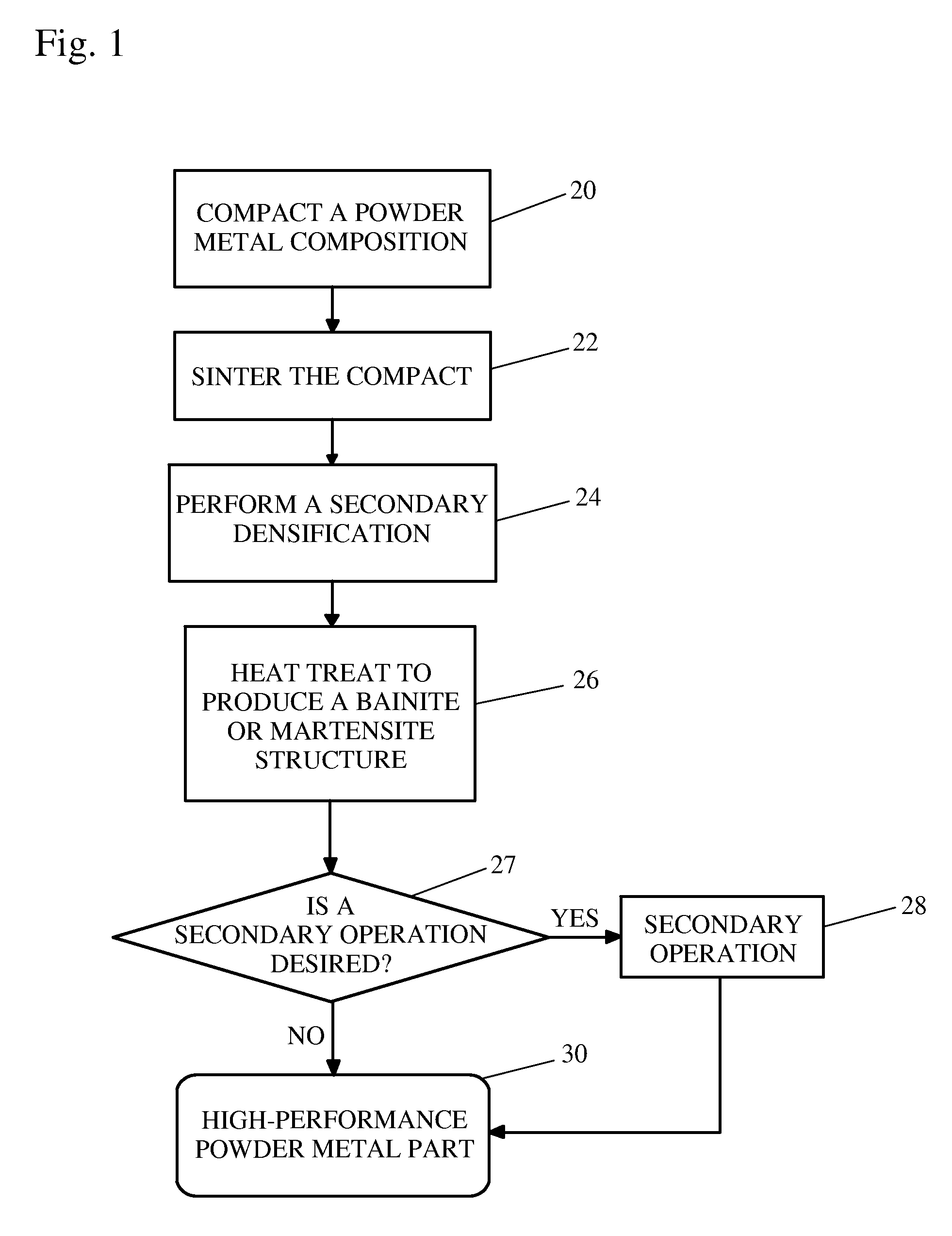
[0037]FIG. 1 shows a method of manufacturing a high-performance powder metal part. A powder metal composition is compacted (20) at a desired pressure to a desired green density. A preferred pressure range is 25 to 65 TSI, and a preferred green density range is 6.4 to 7.4 g / cc. The compaction occurs in the desired shape, or substantially in the desired shape for the final part to be produced. Many powder metal compositions may be used in conjunction with the embodied methods, and their equivalents, disclosed herein. One such preferred powder metal composition has a chemical composition as listed in Table 1. It should be readily understood that other powder metal compositions may be used with the embodied methodologies disclosed herein.

TABLE 1ElementPercentage by Weight (wt %)Cu0-2.0wt %C0.15-0.9wt %Mo0.5-2.0wt %Ni0.5-4.5wt %Cr0-4.0wt %Mn0-1.5wt %Si0-1.5wt %Febalance

[0038] After the powder metal composition is compacted (20), the green compact is sintered (22) at a desired temperature...

second embodiment

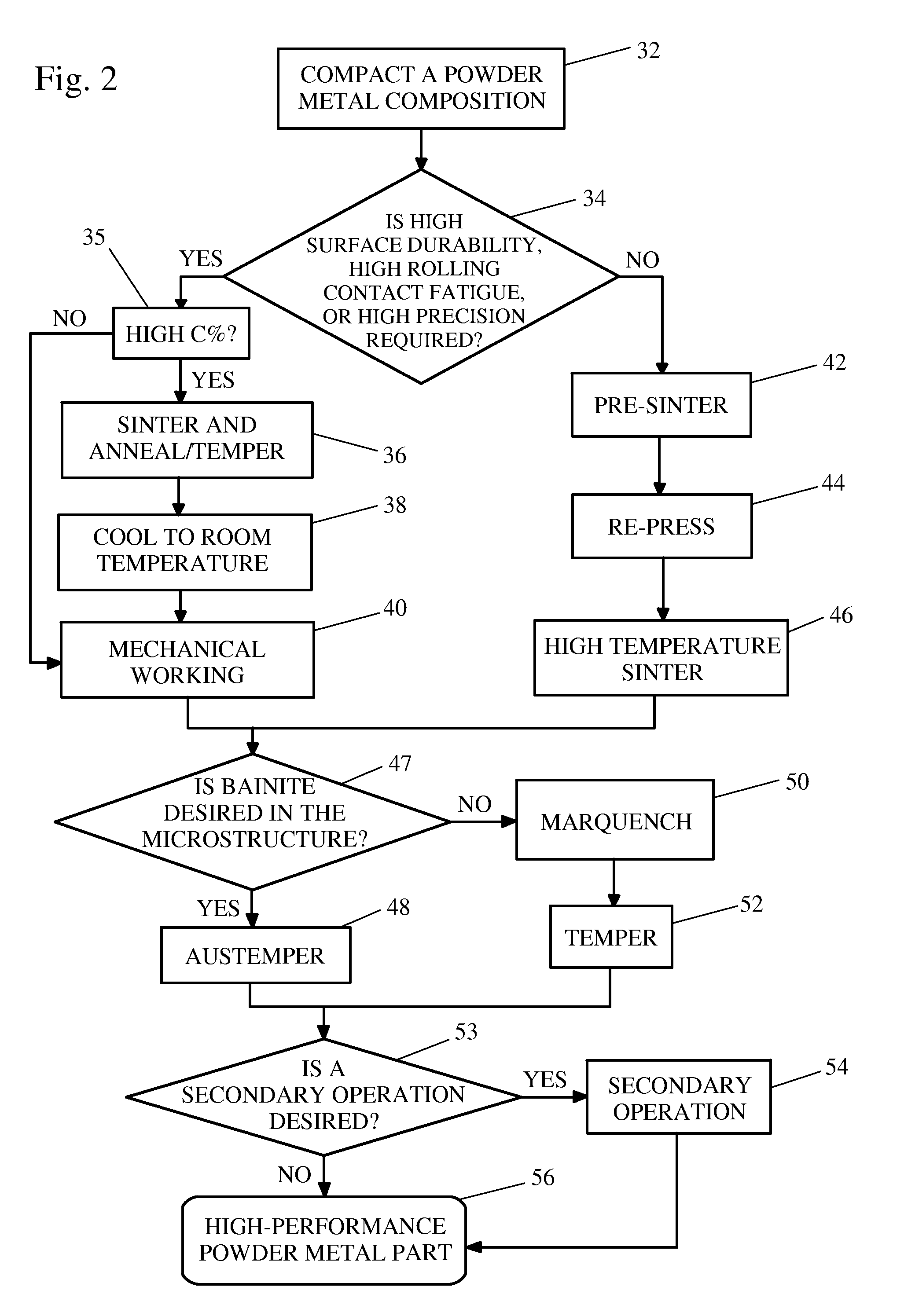
[0039]FIG. 2 shows a method of manufacturing a high-performance powder metal part. First, the powder metal composition is compacted (32) at a desired pressure to a desired green density. The next steps depend on whether or not a high surface durability, high rolling contact fatigue, or high precision is required (34) in the final product. If at least one of these features is required and the metal composition has a high carbon percentage (35), the composition is sintered and annealed / tempered (36), cooled to room temperature (38), and mechanically worked (40). If the powder composition is a low-carbon composition, the substeps of sintering and annealing / tempering (36) and cooling (38) are not necessary and the compact may be directly mechanically worked (40). The part may also be directly worked after sintering to increase the surface density. If none of the final product features is required, the composition is pre-sintered (42), re-pressed (44), and high-temperature sintered (46) ...


PUM

PropertyMeasurementUnit
green densityaaaaaaaaaa
temperatureaaaaaaaaaa

Abstract

A powder metal part is made by compaction at room temperature or an elevated temperature followed by sintering, a secondary densification, heat treating, and optional secondary operations. The particulate materials preferably include iron, 0-2.0 wt % copper, 0.15-0.9 wt % carbon, 0.5-2.0 wt % molybdenum, 0.5-4.5 wt % nickel, 0-4.0 wt % chromium, and 0-1.5 wt % silicon. At least one secondary densification is applied to the part after compaction and pre-sinter/sinters steps to achieve medium to high density. The secondary densification is part of a double-press double-sinter (DPDS) or is a mechanical working depending on the application requirements. The powder metal is heat treated by austempering or marquenching followed by tempering. A unique composite microstructure is achieved from austempering by controlling the powder chemistry and the holding time at an elevated temperature. The combination of a secondary densification and austempering or marquenching produces a high performance powder metal part for demanding applications.

Description

BACKGROUND OF THE INVENTION [0001] 1. Field of the Invention [0002] The invention pertains to the field of powder metallurgy. More particularly, the invention pertains to the formation of a high-performance powder metal part using a manufacturing process including a secondary densification and austempering or marquenching as a heat treatment. [0003] 2. Description of Related Art [0004] Powder metallurgy manufacturing processes have been successfully used to produce powder metal parts while providing various advantages. Such powder metal parts can be made into a variety of complex shapes with minimal steps, and with little or no finishing machining. Powder metallurgy also enables a high-volume of metal parts to be produced in an economic fashion. Powder metallurgy processes have been found to be more energy efficient than other processes involving forging and outright machining. [0005] Secondary densifications of powder metals followed by heat treatment are known in the art. [0006] U...

Claims


Application Information

Patent Timeline
Patent Type & Authority Applications(United States)
IPC IPC(8): B22F1/00B22F1/02
CPCB22F3/16B22F2003/247B22F2003/248B22F2998/10B22F2999/00C22C33/0264B22F3/20B22F3/18B22F3/17B22F3/02B22F3/10B22F1/0085B22F1/142
Inventor XU, KAISUN, RYAN
Owner BORGWARNER INC
Why Eureka
Try Eureka