Lightweight engine

Inactive Publication Date: 2006-09-21
FUKUMOTO TOSHIHIRO +2
View PDF8 Cites 3 Cited by
  • Summary
  • Abstract
  • Description
  • Claims
  • Application Information

AI Technical Summary

Benefits of technology

[0018] According to the present invention, pressurized air or fuel mixture gas with 2 to 4 times or more makes the stroke di

Problems solved by technology

However, there are no technologies using the turbo-charger for the purpose of lightening the engine up to now.
Therefore, a mixture ratio of the fuel of the engine could not be set most appropriate theoreticall

Method used


Image

  • Lightweight engine
  • Lightweight engine
  • Lightweight engine

Examples


Embodiment Construction

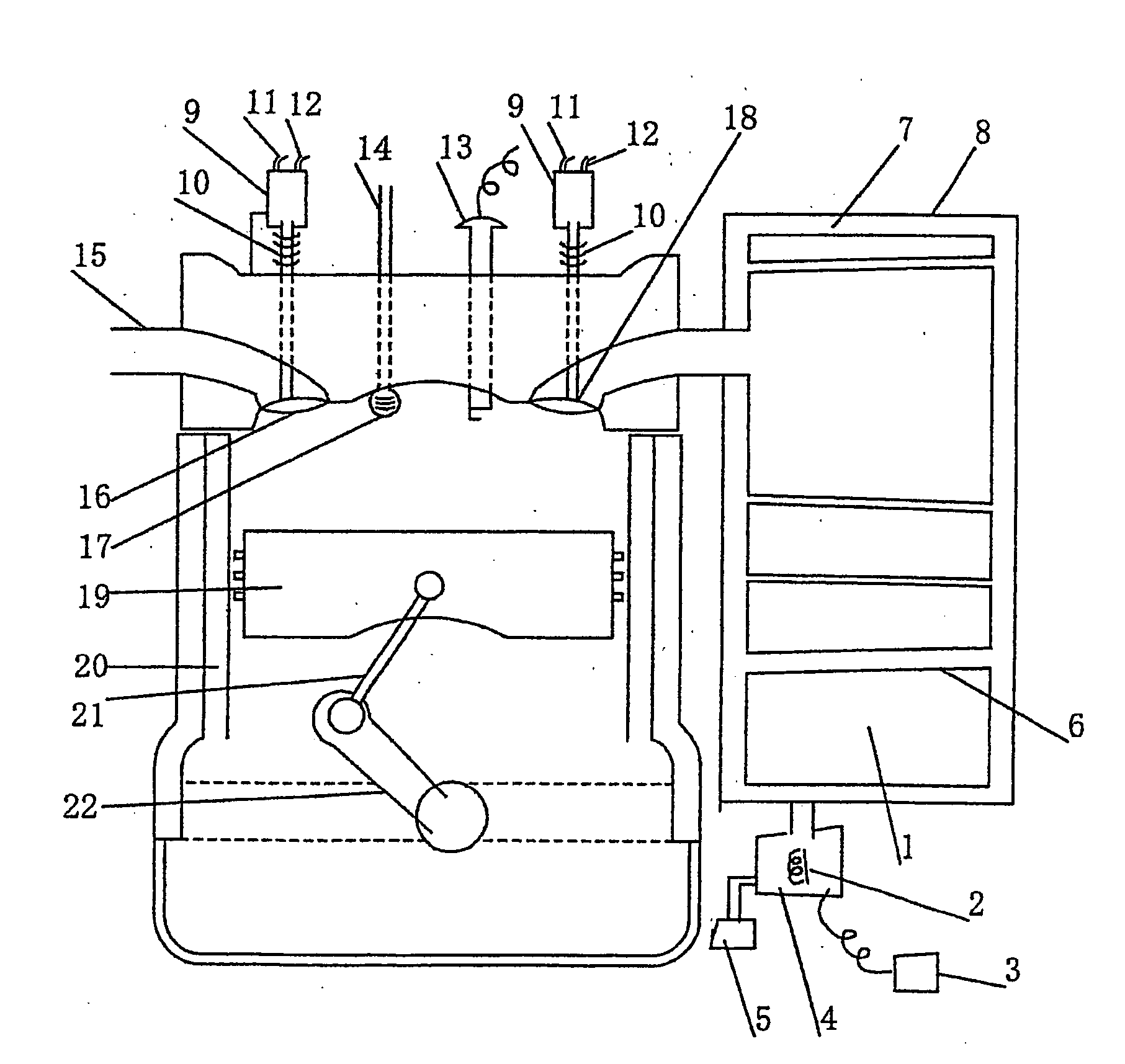
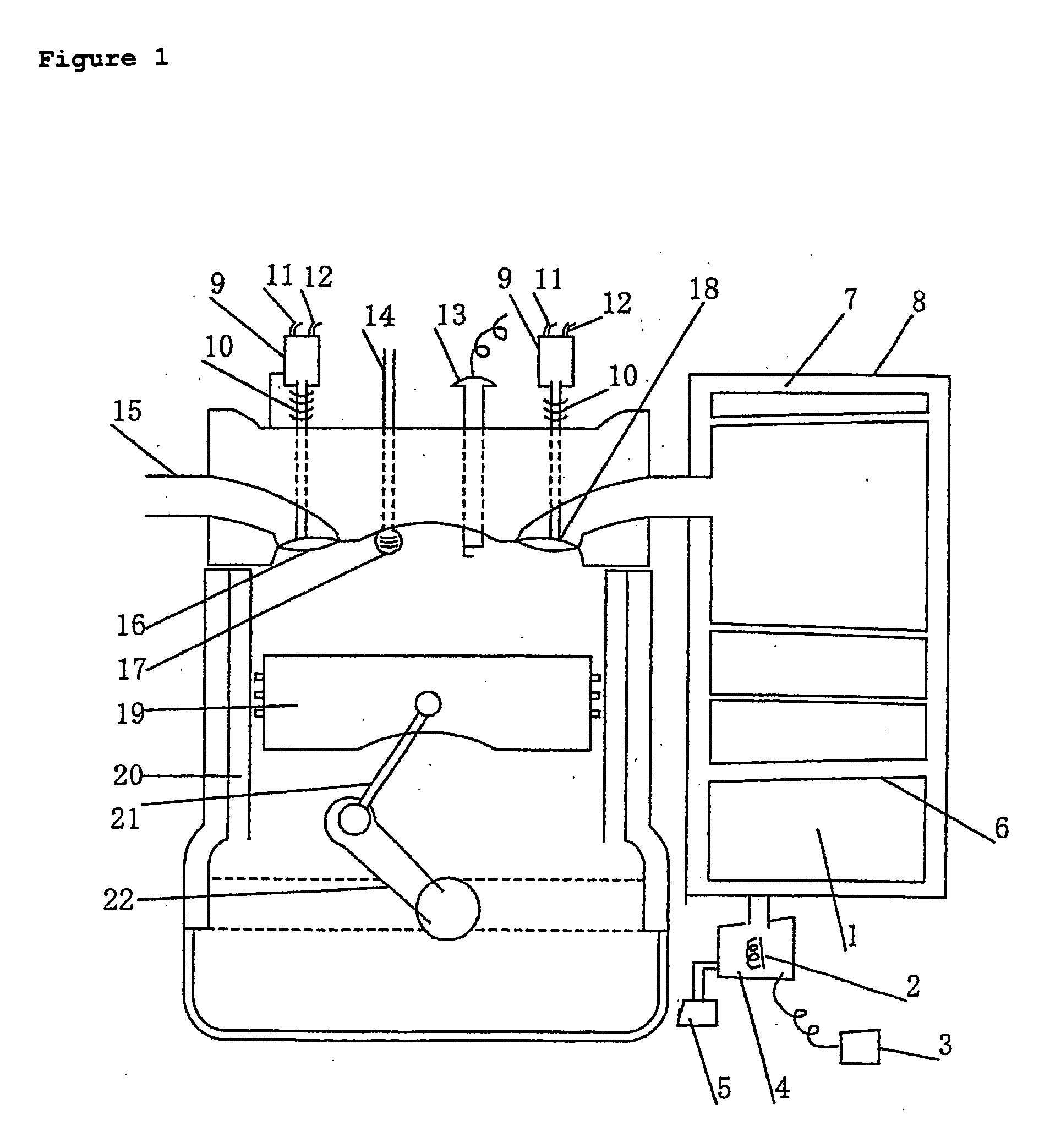
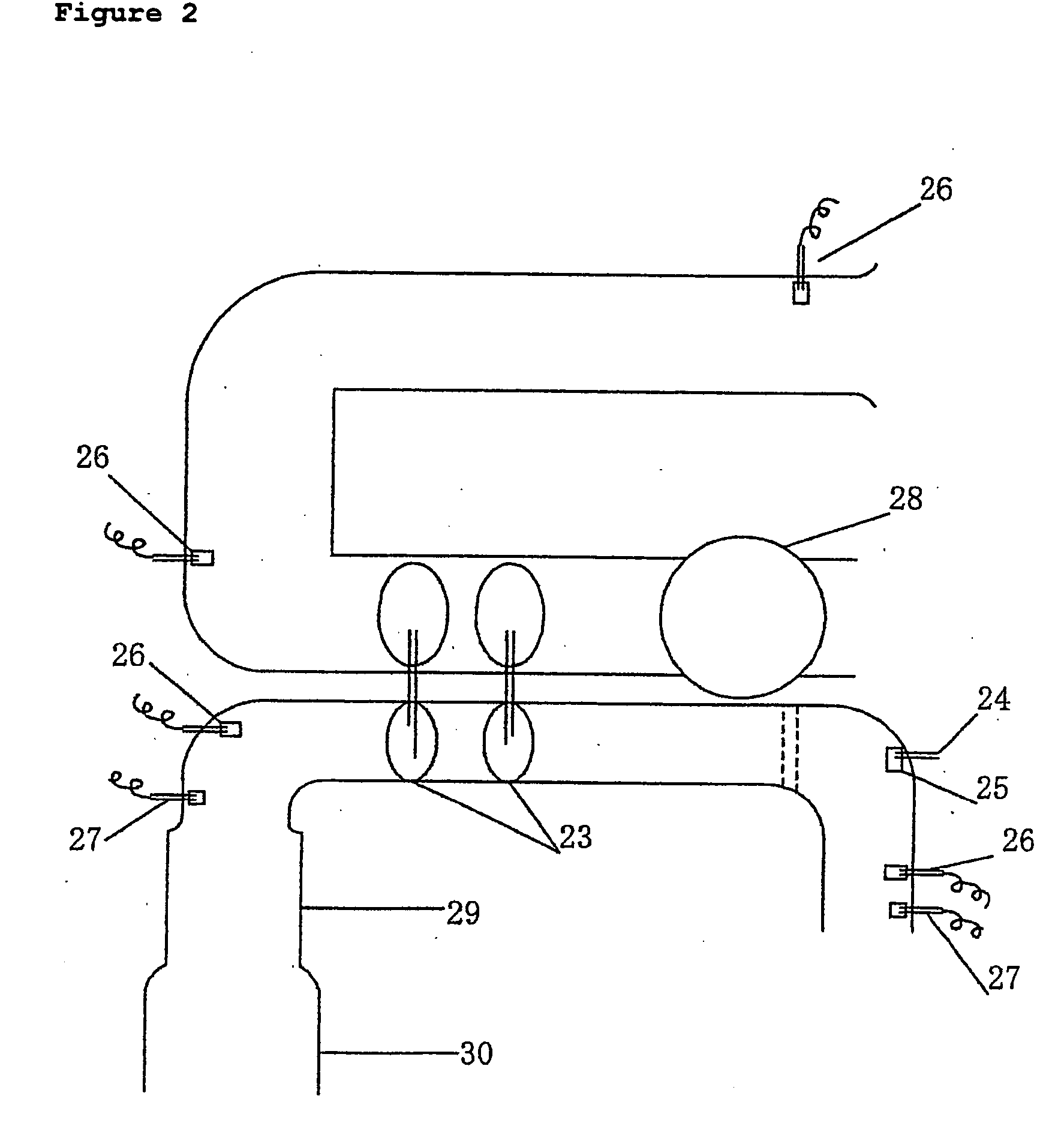
[0029]FIG. 1 is a schematic diagram of the engine. When air is pressurized highly, compression process is decreased. Then total length of the connecting rod (21) and turning radius of the crankshaft (22) is decreased, and the weight is decreased greatly. Additionally, the temperature and the pressure of the air tank (1) can be controlled by the microcomputer reading the numerical value of the sensor located in some areas. Therefore, the burning and the explosion can be controlled stably. And the provision against the exhaust gas, which is nitrogen peroxide gas, carbon monoxide gas, sulfured gas, and unburned fuels, becomes easier. Since the intake gas and the exhaust gas is controlled separately by the motive energy of the oil hydraulics or the electromagnetic force from the microcomputers, operation of the valves can be optimized than ever before and the burning and the explosion can be controlled in line with theoretical figure.

[0030]FIG. 2 is a schematic diagram of the system of...


PUM


Abstract

Weight saving of industrial engines. Making pollution-causing material harmless. Improvement in thermal efficiency and reduction of operating cost. Arrangement To produce compressed air, air is pressurized by a turbo charger or a super turbo charger and stored in an air tank. The air is fed, at an optimum temperature and a given pressure, to a cylinder liner shortened according to the pressure. Valves for taking in and out air are hydraulically driven for individual opening and closing according to a computer-aided optimum valve timing diagram. The engine is controlled under high-oxygen high-temperature lean burn condition, and a hydrocarbon is injected into an exhaust manifold to reduce peroxides, thus making pollution-causing material harmless. Effects Reduction of operating cost. Increase in carrying capacity due to the weight reduction of the vehicle body in the case of a vehicle-mounted engine.

Description

TECHNICAL FIELD [0001] This invention relates to the technology of cars, construction machineries, marine vessels, and electrical generators, which achieves great lightening the engine and the purification of the exhaust gas at the same time. BACKGROUND ART [0002] A pressurizing type engine using the turbo-charger having the intercooler with the low condensation was used for the fighter aircraft in 1940. Thereafter, it was applied for the motor racing such as F1. However, there are no technologies using the turbo-charger for the purpose of lightening the engine up to now. In the past, the principal object of the turbo-charger has been the improvement of the output power, and the purification of the exhaust gas.[0003] There ware few ideas that try to use the exhaust gas in the prior art. There are only ideas such as the actuation of the turbo-charger by the exhaust gas, or the recirculation of the exhaust gas controlling burning temperature to be lower in the liner, etc. [0004] In th...

Claims


Application Information

Patent Timeline
IPC IPC(8): F01N3/00F01L9/10F01N3/20F02B33/44F02B37/00
CPCF01L9/02F01N3/2033F02B33/44F02B37/00Y02T10/26Y02A50/20Y02T10/12F01L9/10
Inventor FUKUMOTO, TOSHIHIROFUKUMOTO, YOUSUKEEBATO, KEIKO
Owner FUKUMOTO TOSHIHIRO
Why Eureka
Try Eureka