Drive apparatus

a drive apparatus and drive motor technology, applied in process and machine control, instruments, data recording, etc., can solve the problems of high noise output of the pwm driver, complex need for faster operation as described above, and extremely weak playback signal output of the optical pickup, so as to improve the usability of the drive apparatus, improve the tolerance for disc warp and eccentricity, and improve the high speed response of the servo

Inactive Publication Date: 2006-10-26
PANASONIC CORP
View PDF6 Cites 7 Cited by
  • Summary
  • Abstract
  • Description
  • Claims
  • Application Information

AI Technical Summary

Benefits of technology

[0027] A drive apparatus according to the present invention can supply control output that is higher than the fixed output by using a step-up type control output generator. The drive output of the drive output generator thus increases when high drive output is needed, the high speed response of the servo thus improves, and drive apparatus usability is improved because the tole...

Problems solved by technology

The need for faster operation as described above is complicated by strong demand for low power consumption.
Noise output by the PWM driver as a result of high frequency current switching is a problem for the optical disc drive, however, and thus requires a separate arrangement for suppressing such circuit emissions.
More particularly, the playback signal output from the optical pickup can be extremely weak in an optical disc drive that can both read and write.
If the PWM driver is used to drive the actuator that moves the objective lens of the optical pickup at this time, electrical noise from the PWM driver will interfere with the playback signal from the optical pickup.
This can result in optical disc drive malfunctions and a higher error rate.
The product of the current times the difference between the power supply voltage and the voltage actually applied to the actuator in the focusing and tracking drive circuits is lost as heat energy in the BTL driver circuit.
However, because a high supply voltage is used for the power supply of the drive circuit, a significant amount of power is wasted and excess heat is generated in the linear drive type BTL drive circuits.
In other words, if the power supply voltage supplying the drive current is high even though the current required to drive the focusing and tracking actuators is low, power consumption by the power output transistors increases, and heat and power consumption by the chips containing the linear dri...

Method used


Image

  • Drive apparatus
  • Drive apparatus
  • Drive apparatus

Examples


second embodiment

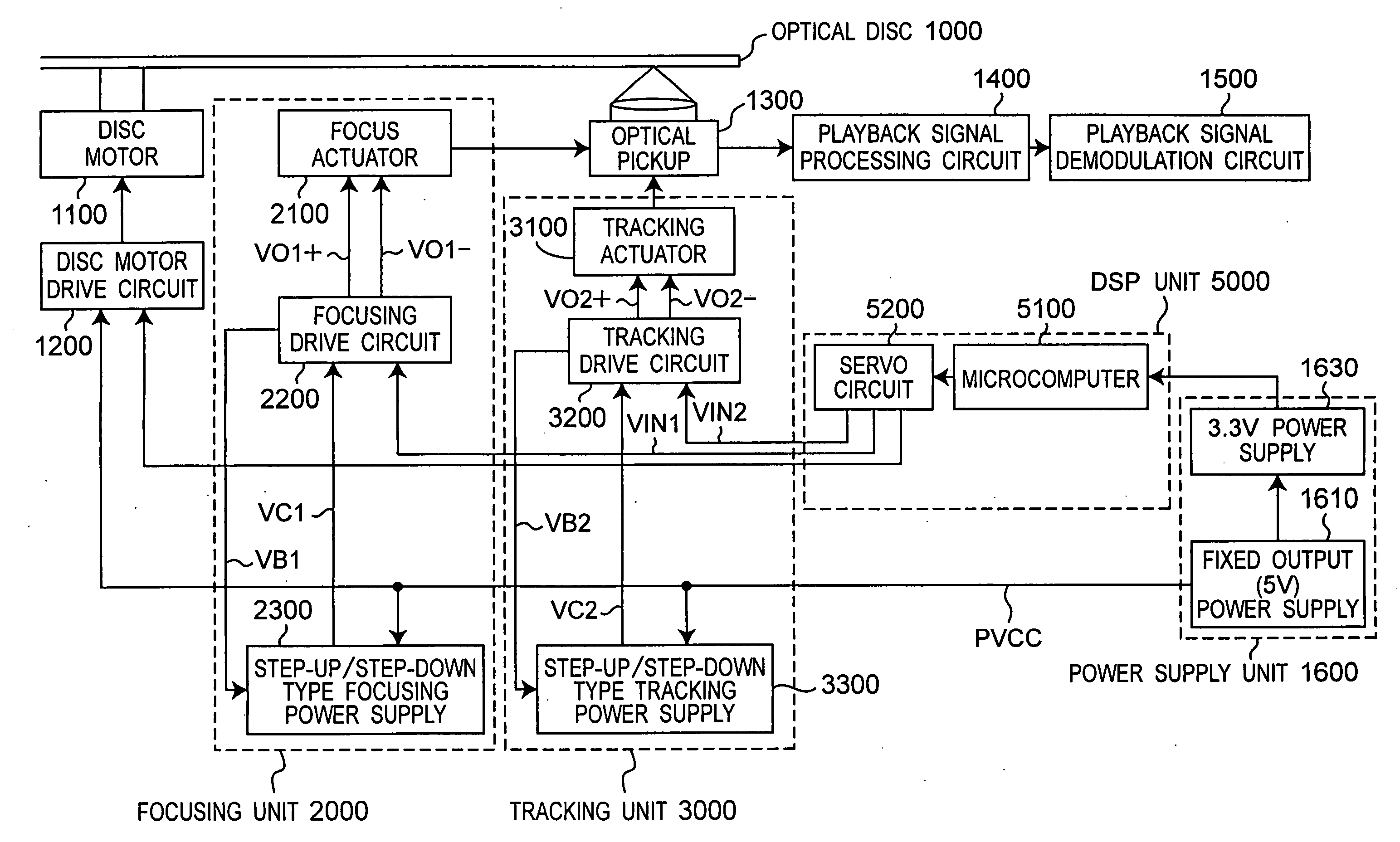
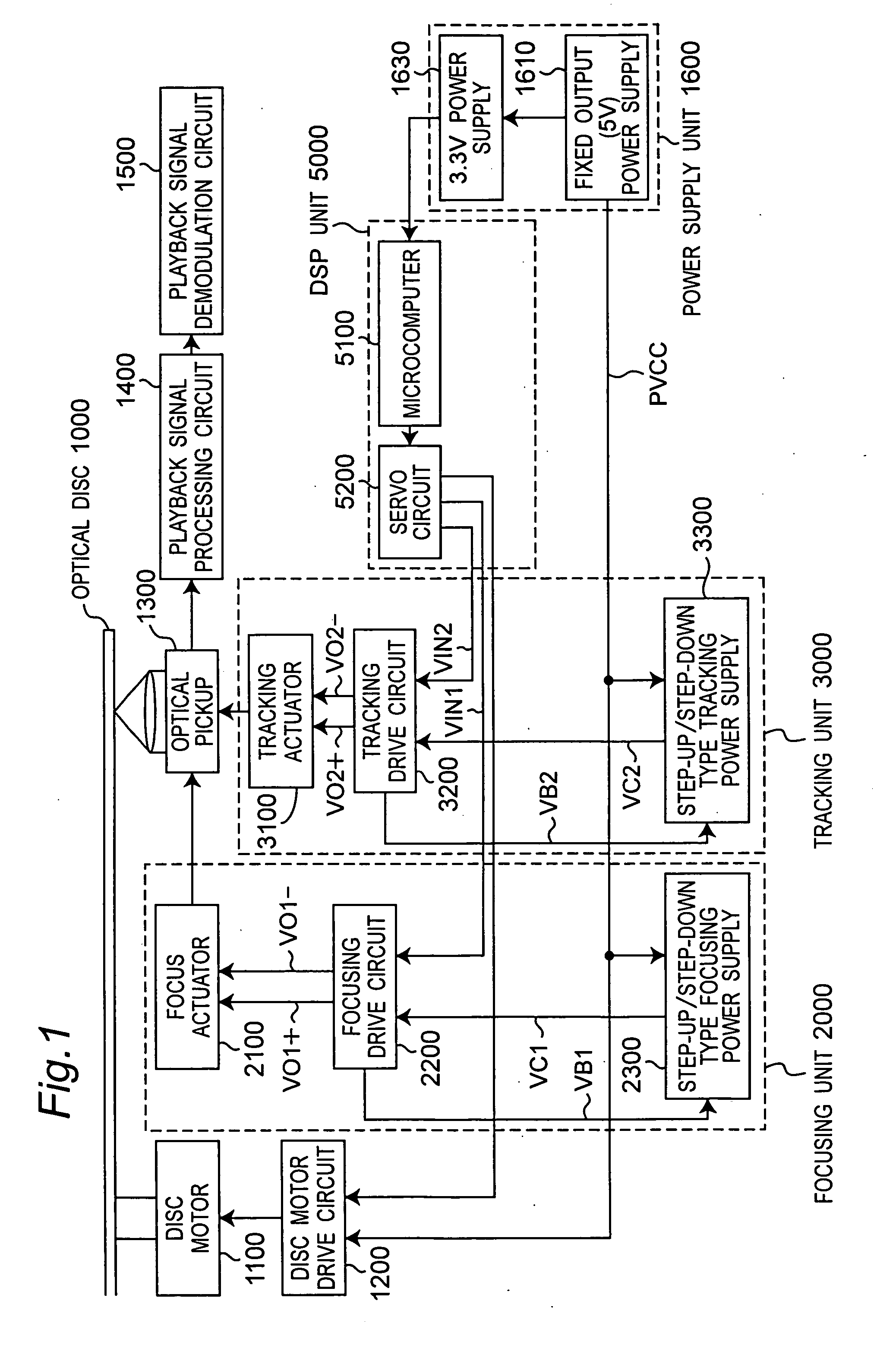
[0158]FIG. 14 is a block diagram of a drive apparatus according to a second embodiment of the invention. FIG. 15 is a block diagram of the drive circuit 4200 in the second embodiment shown in FIG. 14. The second embodiment shown in FIG. 14 differs from the first embodiment shown in FIG. 1 in that the step-up / step-down type focusing power supply 2300 and step-up / step-down type tracking power supply 3300 are combined into a single step-up / step-down power supply 4300, and the focusing drive circuit 2200 and tracking drive circuit 3200 are combined into a single drive circuit 4200.

[0159] While a step-up / step-down power supply 4300 of the same arrangement is provided separately for the focusing unit 2000 and tracking unit 3000 in the first embodiment shown in FIG. 1, the system requires only one in this second embodiment shown in FIG. 14. Therefore, the arrangement, operation, and effect of step-up / step-down type focusing power supply 2300, step-up / step-down type tracking power supply 3...

third embodiment

[0170] In the first and second embodiments of the invention step-up / step-down type focusing and tracking power supplies 2300 and 3300 or step-up / step-down power supply 4300 are used as the power source supplying control output VC1 and VC2 to focusing and tracking drive circuits 2200 and 3200. Third and fourth embodiments of the invention use step-up focusing and tracking power supplies 2300A and 3300A or step-up power supply 4300A.

[0171]FIG. 16 is a block diagram of a drive apparatus according to a third embodiment of the invention.

[0172] The third embodiment shown in FIG. 16 differs from the first embodiment in FIG. 1 in that focusing unit 2000A and tracking unit 3000A are used instead of focusing unit 2000 and tracking unit 3000, respectively, and step-up focusing and tracking power supplies 2300A and 3300A are used instead of the step-up / step-down type focusing and tracking power supplies 2300 and 3300 in the focusing and tracking units 2000A and 3000A. This third embodiment of...

first embodiment

of the Step-Up Type Focusing Power Supply

[0179]FIG. 18 is a detailed block diagram showing a first embodiment of the step-up focusing power supply 2300A in this third embodiment of the invention.

[0180] This first embodiment of the step-up focusing power supply 2300A comprises a step-up DC-DC converter 2350A, and the step-up DC-DC converter 2350A comprises a step-up control circuit 6000A and step-up voltage generator 2338A.

[0181]FIG. 19 is a circuit diagram of the step-up control circuit 6000A.

[0182] The step-up control circuit 6000A comprises a voltage comparator 6100A, sawtooth wave generator 6130A, and PWM comparator 6150A. The voltage comparator 6100A is composed of a voltage amplifier 6110A, resistance RCA, and capacitance CCA.

[0183] The reference voltage input terminal VETA of the step-up control circuit 6000A is connected through the input terminal of the voltage comparator 6100A to the non-inverted input terminal of the voltage amplifier 6110A. The output terminal of the ...


PUM


Abstract

Optical disc drives designed for reduced power consumption switch the supply voltage in three stages between first, second, and third power supplies, but the reduction in power consumption that is possible in the drive circuits with three stage switching control is limited. A drive output tracking signal is generated according to the waveform of the drive output that drives the focus and tracking actuators, and this drive output tracking signal is applied to a step-up type focusing and tracking power supply. The step-up power supply controls the fixed output according to the drive output tracking signal, and when the drive output is greater than the fixed output, control output that is greater than or equal to the fixed output and slightly greater than the drive output is generated. This control output is supplied to the focus and tracking drive circuits to produce drive output.

Description

BACKGROUND OF THE INVENTION [0001] 1. Field of Technology [0002] The present invention relates to a drive apparatus for use in devices such as optical disc recording and playback drives, and relates more particularly to technology for reducing power consumption by the drive circuit while increasing the drive speed by improving the drive performance of the drive circuit. [0003] 2. Description of Related Art [0004] Optical disc media offer numerous benefits, including long media life as a result of non-contact recording and reading, random accessibility enabling significantly faster access to desired content than is possible with magnetic tape, and a large storage capacity. Disc drives for reading and / or writing Compact Disc (CD) and DVD (digital versatile disc) media have thus become standard equipment on most personal computers sold today. In order to meet the demand for ever higher data transfer rates, faster disc motors are being used to rotationally drive the optical discs. [0005...

Claims


Application Information

Patent Timeline
IPC IPC(8): G05B1/06
CPCG11B7/0953G11B19/02G11B7/0956
Inventor FUKAMIZU, SHINGOYAMAMOTO, YASUNORI
Owner PANASONIC CORP
Why Eureka
Try Eureka