Visible-light-responsive photoactive coating, coated article, and method of making same

a photoactive coating and visible light technology, applied in the direction of catalyst activation/preparation, physical/chemical process catalysts, natural mineral layered products, etc., can solve the problems of inability to meet certain application conditions or substrates economically or practically, and the sol-gel coating method is not economically or practically compatible with certain application conditions or substrates, etc., to achieve the effect of reducing or eliminating at leas

Inactive Publication Date: 2006-11-23
PPG IND OHIO INC
View PDF99 Cites 26 Cited by
  • Summary
  • Abstract
  • Description
  • Claims
  • Application Information

AI Technical Summary

Benefits of technology

[0055] Advantages of the present invention over the ion-implantation and sol-gel methods of forming self-cleaning coatings include an ability to form a thin, dense, PM film on a substrate as opposed to the generally thicker, porous self-cleaning coatings obtained with the ion-implantation and sol-gel coating methods. Still another advantage is that the method of providing a PM coating according to the present invention avoids the need to reheat the substrate after application of the coating or coating precursor as is practiced in the conventional ion-implantation and sol-gel methods. Not only does this render the present method less costly and more efficient, e.g., less equipment costs, less energy costs, and less production time, but also the opportunity for sodium ion migration and in turn sodium ion poisoning of the PM coating 24 of the present invention is significantly reduced. Further still, the method of the present invention is easily adapted to the formation of PM coatings on continuous moving substrates, such as a glass float ribbon.
[0056] It will be readily appreciated by those skilled in the art that modifications can be made to the invention without departing from the concepts disclosed in the foregoing description. Accordingly, the particular embodiments described in detail herein are illustrative only and are not limiting to the scope of the invention, which is to be given the full breadth of the appended claims and any and all equivalents thereof.

Problems solved by technology

This approach can be labor, time, and / or cost intensive.
A problem with these conventional PC coatings is that they typically exhibit photoactivity or photocatalysis only upon exposure to ultraviolet (UV) light in wavelengths shorter than about 380 nanometers (nm).
However, these ion implantation and sol-gel coating methods are not economically or practically compatible with certain application conditions or substrates.
For example, in a conventional float glass process, the float glass ribbon in the molten metal bath can be too hot to accept the sol due to evaporation or chemical reaction of the solvent used in the sol.
Reheating to a temperature sufficient to calcinate the coating or form the crystallized photocatalyst can require a substantial investment in equipment, energy, and handling costs, and can significantly decrease production efficiency.
This migration can result in what is conventionally referred to as “sodium ion poisoning” of the deposited coating.
Moreover, the ion-implantation and sol-gel methods typically result in thick coatings, e.g., several microns thick, which may have an adverse effect on the optical and / or aesthetic properties of coated articles.
Thus, coatings thick enough to provide the desired self-cleaning properties can have undesirable optical characteristics.

Method used


Image

  • Visible-light-responsive photoactive coating, coated article, and method of making same
  • Visible-light-responsive photoactive coating, coated article, and method of making same
  • Visible-light-responsive photoactive coating, coated article, and method of making same

Examples


Embodiment Construction

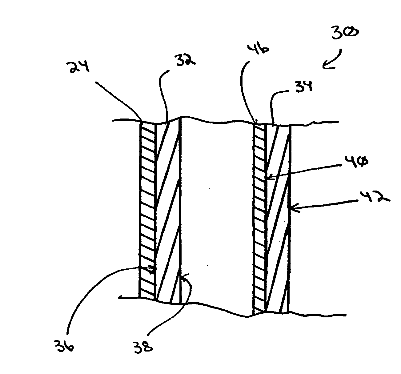
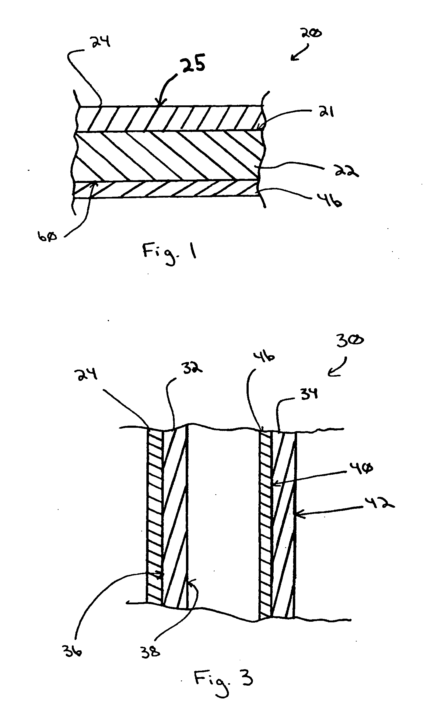
[0018] As used herein, spatial or directional terms, such as “inner”, “outer”, “above”, “below”, “top”, “bottom”, and the like, relate to the invention as it is shown in the drawing figures. However, it is to be understood that the invention can assume various alternative orientations and, accordingly, such terms are not to be considered as limiting.

[0019] Further, all numbers expressing dimensions, physical characteristics, processing parameters, quantities of ingredients, reaction conditions, and the like used in the specification and claims are to be understood as being modified in all instances by the term “about”. Accordingly, unless indicated to the contrary, the numerical values set forth in the following specification and claims are approximations that can vary depending upon the desired properties sought to be obtained by the present invention. At the very least, and not as an attempt to limit the application of the doctrine of equivalents to the scope of the claims, each ...


PUM

PropertyMeasurementUnit
contact angleaaaaaaaaaa
wavelengthsaaaaaaaaaa
surface areaaaaaaaaaaa

Abstract

A method is provided for forming a photoactive coating having a photoabsorption band in the visible region of the electromagnetic spectrum. The method includes depositing a precursor composition over at least a portion of a float glass ribbon in a molten metal bath by a CVD coating device. The precursor composition includes a titania precursor material and at least one other precursor material selected from chromium (Cr), vanadium (V), manganese (Mn), copper (Cu), iron (Fe), magnesium (Mg), scandium (Sc), yttrium (Y), niobium (Nb), molybdenum (Mo), ruthenium (Ru), tungsten (W), silver (Ag), lead (Pb), nickel (Ni), rhenium (Re), and mixtures thereof.

Description

CROSS-REFERENCE TO RELATED APPLICATIONS [0001] This application is a continuation-in-part of U.S. Application No. 10 / 075,316 to Greenberg et al., entitled “Photocatalytically-Activated Self-Cleaning Appliances”, filed Feb. 14, 2002, which is a divisional of U.S. application Ser. No. 09 / 282,943 filed Apr. 1, 1999 (now U.S. Pat. No. 6,413,581), which is a divisional of U.S. application Ser. No. 08 / 899,257, filed Jul. 23, 1997 (now U.S. Pat. No. 6,027,766), which claimed the benefit of U.S. Provisional Application Ser. No. 60 / 040,566, filed Mar. 14, 1997, all of which applications are herein incorporated by reference in their entirety. This application also claims the benefit of U.S. Provisional Application Ser. No. 60 / 305,057 filed Jul. 13, 2001, which is herein incorporated by reference in its entirety.FIELD OF THE INVENTION [0002] The present invention relates to methods of depositing photoactive coatings on a substrate (e.g., a glass sheet or a continuous float glass ribbon), to me...

Claims


Application Information

Patent Timeline
Patent Type & Authority Applications(United States)
IPC IPC(8): B32B17/06B32B15/00B32B9/00B01J35/02B01J37/02B01J37/34C03B18/14C03C17/00C03C17/245C03C17/25C03C17/34C23C14/48C23C16/40
CPCC03C2217/212Y10T428/265C03C2217/71C03C2218/112C03C2218/152C03C2218/154C03C2218/155C03C2218/156C03C2218/32C03C2218/365C23C16/40Y02T50/67C03C17/245C03C17/2456C03C17/25C03C17/256C03C17/3417C03C17/3435C03C17/3441Y10T428/315C03C2217/24Y10T428/31678Y02T50/60
Inventor GREENBERG, CHARLES B.SZANYI, JANOS
Owner PPG IND OHIO INC
Why Eureka
Try Eureka