Distillation methods and devices in particular for producing potable water

a technology of distillation method and potable water, which is applied in the direction of vacuum distillation separation, vessel construction, separation process, etc., can solve the problems of scarcely being able to establish significant thermal conductance between, poorly defined thermal conductance connection, and inability to achieve significant thermal conductance, etc., to achieve optimum compactness, reduce weight and intrinsic stability, and high efficiency

Inactive Publication Date: 2006-12-07
THE THIRD MILLENIUM WATER
View PDF2 Cites 43 Cited by
  • Summary
  • Abstract
  • Description
  • Claims
  • Application Information

AI Technical Summary

Benefits of technology

[0175] According to another invention of Jean-Paul DOMEN, which is the subject of the international PCT Patent Application entitled “Heat exchanger. Methods and means of producing this exchanger”, filed under No. Fr 03 / 03692, 12th December 2003, by “TECHNOLOGIES DE L'ECHANGE THERMIQUE”, a compact counter-current heat exchanger, in particular for confined fluids, is described which provides particularly advantageous conditions of implementation for the third embodiment of the present invention. In fact, this new heat exchanger combines on the one hand, four significant technical characteristics, namely: high efficiency, optimum compactness, reduced weight and intrinsic stability and, on the other hand, an essential economic characteristic, which the heat exchangers currently available on the market do not have, namely, a low production cost. Such a heat exchanger is particularly well suited to the standard heat exchange requirement of the four embodiments of the present invention. Moreover, this new type of exchanger makes it possible, by means of an improvement according to the present invention, to design a new architecture for a vapour-diffusion and heat-transfer gas still according to the third embodiment of the invention. This multiplies the benefit and advantageously makes it possible to replace the large, flexible or rigid, rectangular heat-exchange plates described in the PCT Application referred to at the beginning of the present document.
[0176] According to the PCT Application concerned, an elementary monobloc heat exchanger with high efficiency, limited space requirement, reduced weight, low production cost and, generally, intrinsic stability,

Problems solved by technology

This scarcely makes it possible to establish a significant thermal conductance between them.
This scarcely appears to be possible with the elements of the AVP solar still, which have complex geometries and very weak and poorly-defined thermal conductance connections.
Such a statement is correct in certain cases, but as will be seen below, its generalization leads to conclusions which are simplistic and incomplete in certain cases and even false in other cases.
But this is not at all the case for the distillation heat exchanges which occur in vapour-diffusion stills.
And, in the case where this energy is inexpensive (solar or co-generation from the cooling liquid or exhaust gas from heat engines), a lower COP will be chosen and therefore a limited investment (fewer heat-exchange plates).

Method used


Image

  • Distillation methods and devices in particular for producing potable water
  • Distillation methods and devices in particular for producing potable water
  • Distillation methods and devices in particular for producing potable water

Examples


first embodiment

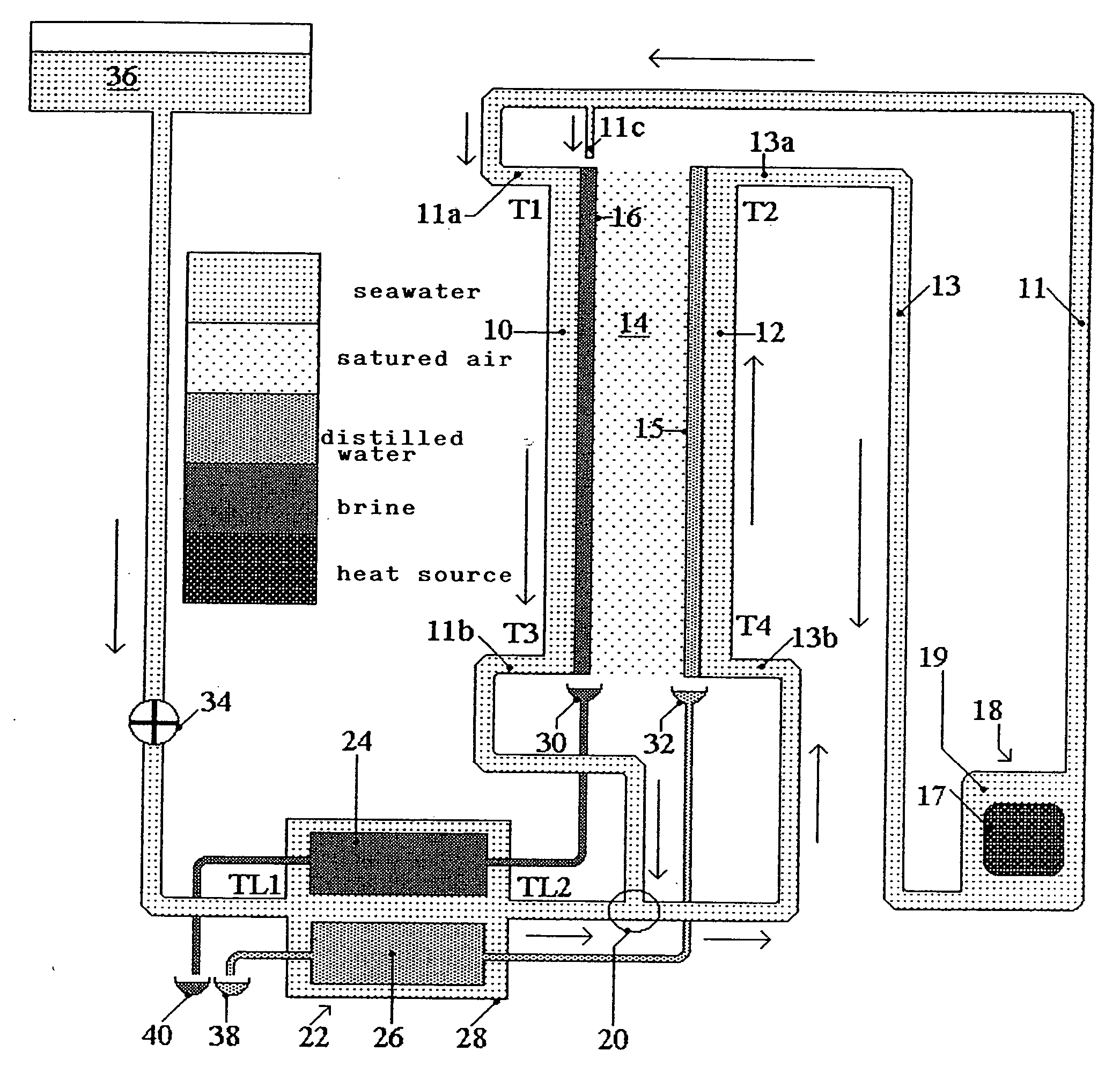
[0202] According to the diagram in FIG. 3, which constitutes a still according to the invention, two plates 10, 12 symbolically represent a vapour-diffusion distillation and heat-transfer-liquid unit, constituted by a set of large rigid cellular plates (50 to 150 dm2), rectangular in shape, installed in the treatment chamber of a vapour-diffusion and heat-transfer-liquid still, according to the present invention. These hollow plates 10, 12 have a small internal thickness (2 to 3 mm for example) and are separated from each other by a narrow free space 14, having a thickness of approximately 5 mm, filled with a non-condensable gas, in particular air at atmospheric pressure. The hollow plate 10 is referred to as hot since it is assigned to the evaporation of the liquid to be distilled and, to this end, it is provided with a hydrophilic or wettable coating 16. The hollow plate 12 is referred to as cold since it is assigned to the condensation of the vapour diffused in the non-condensabl...

second embodiment

[0205]FIG. 4 represents a diagram of a vapour-diffusion still, according to the invention, in which the direction of circulation of the heat-transfer liquid in the hot plates is from the bottom upwards, the reverse of that in FIG. 3. Consequently, the components of the two distillation units in FIGS. 3 and 4 are identical, and the diagram is more or less symmetrical to that in FIG. 3, their other components being identical or equivalent. They have been given all the same numerical references, with however an additional sign (′) for those in FIG. 4. This is in order to differentiate them from each other, the ways in which they are connected together being different. The inlet to the hot hollow plate 10′ is connected, by its bottom coupling 11′a and a duct 11′, to the outlet from the heating chamber 19′ of a boiler 18′ equipped with a heating tube 17′. The outlet from the hot plate 10′ is connected, by its top coupling 11′ b, to one of the inlets to a mixer 20′, the other inlet to whi...

third embodiment

[0208]FIG. 5 is a flow diagram of a first vapour-diffusion still using air, saturated with vapour of the liquid to be distilled, as heat-transfer fluid. It has the characteristic of causing the air to circulate inside hollow distillation plates from the top downwards. This device constitutes a still according to the invention.

[0209] According to this FIG. 5, the internal 50 and external faces 52 of one of the two walls of a large rectangular hollow distillation plate 54 respectively border its internal volume 56 and the free space 58 which separates two adjacent plates. This plate 54 symbolically represents a vapour-diffusion and heat-transfer-gas distillation unit, constituted by a large number N of flexible or rigid hollow distillation plates, separated by narrow inter-plate spaces. The external face 52 of the wall of the plate 54 comprises a hydrophilic coating 60. In the vicinity of these first N hollow plates, a reduced number n of auxiliary hollow plates for preheating the liq...


PUM

PropertyMeasurementUnit
temperature T3aaaaaaaaaa
temperature T1aaaaaaaaaa

Abstract

The inventive device is embodied in the form of a chamber-oven for diffusing vapour and saturated hot air which circulate in a closed circuit by natural convection. Said device is embodied in the form of a domestic-use solar energy collecting device provided with a greenhouse whose surface is equal to 1 m2 and produces from 50 to 100 litres/day of distilled water. The device comprises a distillation unit arranged between two furnaces (59′, 79′) in a temperature-controlled container (48′). Said distillation unit comprises 100 flat thin hollow plates having a surface of 20 dm2 by face and an active volume of 200 dm3. The fine and tensioned walls (54) of said plates are provided with a hydrophilic coating (60′) and internal (56′) and inter-plate (58′) spaces. The lower chimney (59′) comprises a greenhouse (118′, 119′) whose bottom is embodied in the form of an impermeable black layer provided with a thin hydrophilic carpet on the rear part thereof. Saturated hot air at a temperature of 80° C. enters inside (56′) hollow plates from bellow and exits from the top at a temperature of 50° C. A high chimney (79′) is provided with a monoblock heat exchanger (84′) which is transversed by a non-potable water to be distilled which, afterwards is spread warm (40° C.) over the hydrophilic coating (60′). During passage through the heat exchanger (84) the air is cooled to 30° C. and moved down by gravity to the inter-plate spaces (58′) and exits therefrom at a temperature of 78° C. The distilled water condensed in the plates and by the heat exchanger is collected and removed. Brine is received in the bottom of the inter-plate space and distributed along the thin hydrophilic carpet of the bottom (122′) of the greenhouse. An air current passes along said hot carpet is heated and saturated and enters the plates. The brine liquor finally flows in an air-preheating tank (63′) which is emptied each morning. The greenhouse can be substituted by a heating tube transversed by a heating fluid or associated with another steam-jet tube. The more powerful chamber-ovens can produce at least 200 m3/day of distilled water for collective consumption. Said invention can be used for salt removal from seawater, co-generating electricity and potable water and for producing food concentrates.

Description

BACKGROUND OF THE INVENTION [0001] The present invention, resulting from the collaboration of Jean-Paul DOMEN and Stéphane VIANNAY, relates to improvements to a prior invention of the first-named, relating to distillation methods and devices, described in an international PCT Patent Application, filed by the applicant and published on 20th Dec. 2001 under No. WO 01 / 96244 A1. This PCT Application describes a general multiple-effect distillation method, intended to separate substances in solution from their liquid solvent, as well as two methods and particular stills. [0002] These distillation methods and devices are chiefly intended for producing fresh water, easily transformable into potable water. They use low-temperature heat sources of various types (usual boiler, solar boiler or heat engine radiator) and treat most types of non-potable water, such as seawater, brackish groundwater or clear but polluted surface water. To this principal application are added those relating to the ...

Claims


Application Information

Patent Timeline
Patent Type & Authority Applications(United States)
IPC IPC(8): C02F1/04B01D1/00B01D1/22B01D1/30B01D3/34C02F1/14
CPCB01D1/0047B01D1/007B01D1/221C02F2103/08B01D3/346C02F1/04C02F1/14B01D1/30Y02W10/37Y02A20/142Y02A20/211Y02A20/212Y02A20/124Y02P70/10
Inventor DOMEN, JEAN-PAULVIANNAY, STEPHANE
Owner THE THIRD MILLENIUM WATER
Why Eureka
Try Eureka