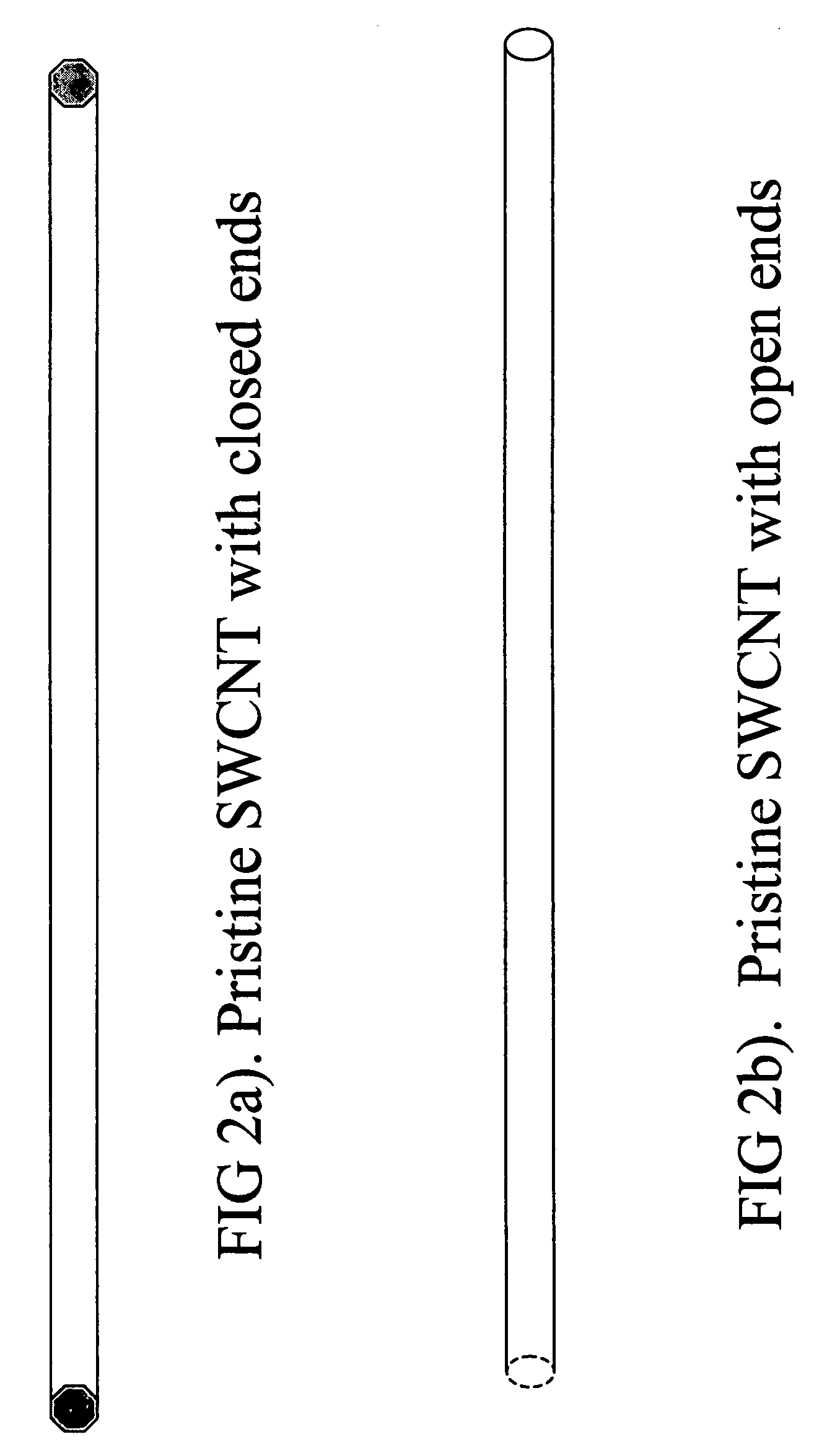
However, these end caps may be removed via appropriate
processing techniques leaving uncapped tubules.
Thus, SWCNTs have been extremely difficult to process for various uses.
This method does not provide opportunities for
solvent based
processing and is limited to
melt extrusion which can limit opportunities for patterning or device making.
The chemically bonded polymers identified typically have high molecular weights and could interfere with some material properties of the SWCNTs (e.g. electronic or
thermal transport) via wrapping around the SWCNTs and preventing tube-tube contacts.
The conductivities achieved in these
polymer composites are several orders of magnitude too low and not optimal for use in most electronic devices as electronic conductors or EMI shields.
Additionally, the organic solvents used are toxic, costly and
pose problems in processing.
Moreover, the polymers used or polymerized are not conductive and can impede tube-tube contact further increasing the resistivity of the composite.
This method is problematic as it needs extremely large levels of surfactant to solubilize the SWCNTs.
The surfactant is insulating and impedes
conductivity of a film deposited from this composition.
The surfactant may be washed from the film but this step adds complexity and may decrease efficiency in processing.
Further, due to the structure formed in films deposited from such a composition, it would be very difficult to remove all the surfactant.
These materials may not provide the highly transparent and highly conductive (low
sheet resistance, RS) layer that is necessary in many current electronic devices, especially displays.
Such low concentrations are impractical and unusable for most deposition techniques useful in high quantity manufacturing.
Further, such high liquid loads need extra
drying considerations and can destroy patterned images due to intermixing from the excess
solvent.
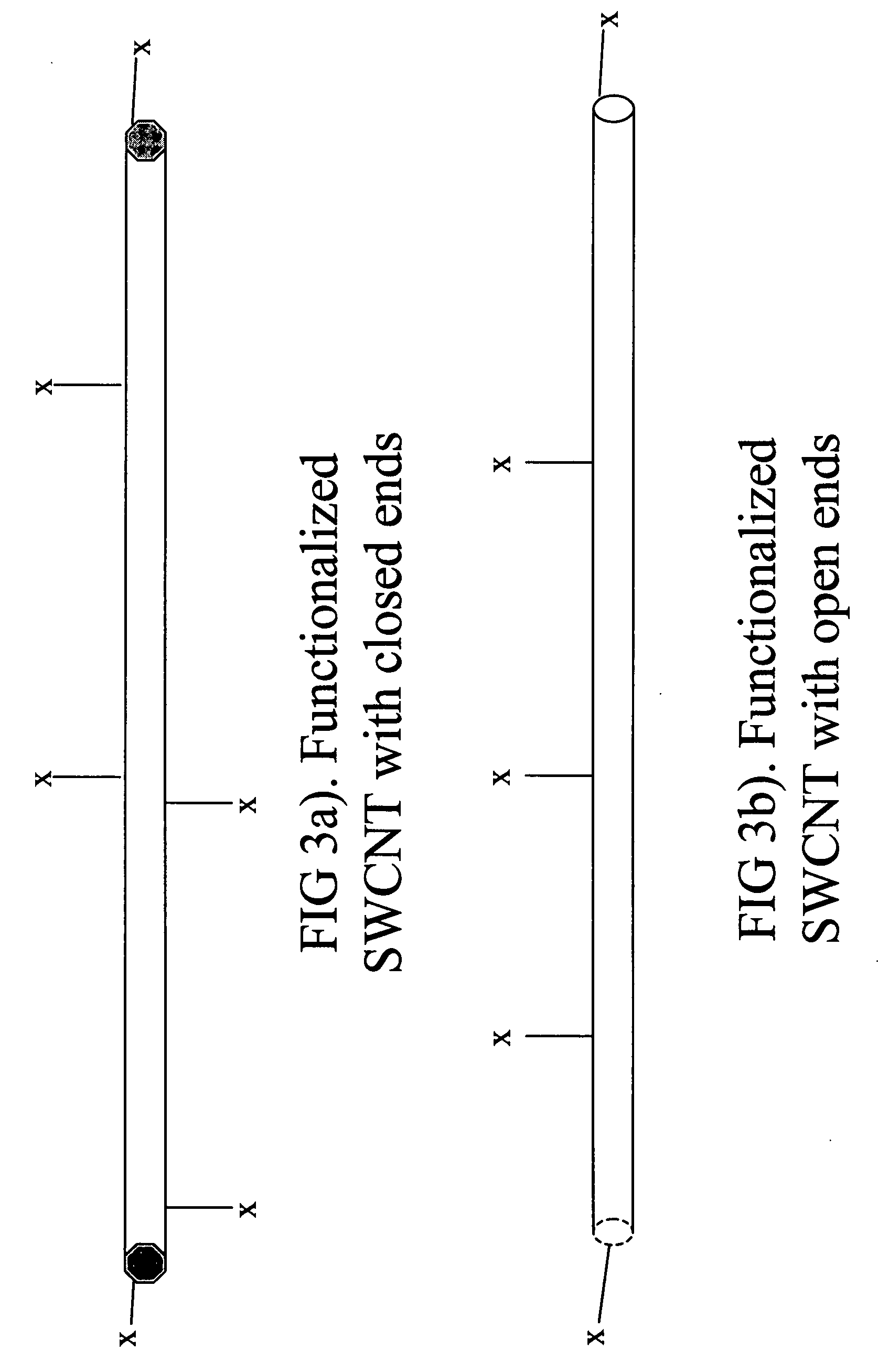
In addition, the method discloses functionalization of the
tubule ends with various functionalization groups (acyl,
aryl, aralkyl,
halogen,
alkyl, amino,
halogen,
thiol) but the end functionalization alone may not be enough to produce viable dispersions via solubilization.
Further, the side-wall functionalization is done with
fluorine only, which gives limited
solubility in alcohols, which can make manufacturing and product fabrication more difficult.
Additionally, the fluorinated SWCNTs are insulators due to the fluorination and thereby are not useful for electronic devices especially as electronic conductors.
Moreover, the chemical transformations needed to add these functional groups to the end points of the SWCNTs require additional processing steps and chemicals which can be hazardous and costly.
Such low concentrations are impractical and unusable for most deposition techniques useful in high quantity manufacturing.
Further, such high liquid loads need extra
drying considerations and can destroy patterned images due to intermixing from the excess
solvent.
In addition, the method discloses functionalization of the
tubule ends with various functionalization groups (acyl,
aryl, aralkyl,
halogen,
alkyl, amino, halogen,
thiol) but the end functionalization alone may not be enough to produce viable dispersions via solubilization.
Moreover, the chemical transformations needed to add these functional groups to the end points of the SWCNTs require additional processing steps and chemicals which can be hazardous and costly.
Also, the patent discloses a composition of matter which is at least 99% by weight of single wall carbon molecules which obviously limits the amount of functionalization that can be put onto the SWCNTs thereby limiting its solubilization levels and processability.
This method is disadvantaged since it needs a
porous membrane (e.g.
polycarbonate or mixed
cellulose ester) with a high volume of
porosity with a plurality of sub-micron pores as a substrate which may lose a significant amount of the SWCNT dispersion through said pores thereby
wasting a significant amount of material.
Also, such membranes may not have the
optical transparency required for many electronic devices such as displays.
Further, the membrane is set within a vacuum
filtration system which severely limits the processability of such a
system and makes the roll-to-roll
coating application of the SWCNT solution impossible.
Such weight percents are impractical and unusable in most
coating and deposition systems with such a high liquid load.
Such high liquid loads make it virtually impossible to make patterned images due to solvent spreading and therefore image bleeding / destruction.
PANI is a highly
colored conductive polymer thus resulting in a conductive composite with unsatisfactory transparency and color, thus it is not suitable for high transparency /
high conductivity applications such as displays.
Further, the
conductivity values are not suitable for many electronic device applications.
In addition, the compositions are made in organic solvents, which may require special handling for health and safety, making manufacturing difficult and expensive.
The dispersion concentrations used in these methods make it very difficult to produce images via direct deposition (inkjet etc.) techniques.
Further, such high solvent loads due to the low solids dispersions create long process times and difficulties handling the excess solvent.
In addition, these patterning methods are subtractive processes, which unnecessarily waste the SWCNT material via additional removal steps thereby incurring cost and
process time.
This application also discloses method to make conductive compositions and coatings from such compositions but it does not teach satisfactory methods nor compositions to execute such methods.
The high cost of the fabrication methods and the low flexibility of such electrodes, due to the
brittleness of the inorganic ITO layer as well as the glass substrate, limit the range of potential applications.
Such methods that involve conventional lithographic techniques are cumbersome as they involve many steps and require the use of hazardous chemicals.
However, the transparency vs. surface electrical resistivity of such products may not be sufficient for some applications.
However, the conductivity requirement for these films appears to be not very stringent.
Such an involved process may be difficult to practice for roll-to-roll production of a wide flexible plastic substrate.
As mentioned earlier, such processes are difficult to implement for roll-to-roll production of conductive coatings.
But, health and safety concerns will dictate special precautionary measures, which may need to be taken, for the introduction of such hazardous compounds to a typical web manufacturing and coating site, thus possibly adding cost to the final product.
However, ITO tends to crack under stress and its conductivity altered.
More flexible conductive polymers have also been considered for this application, but these conductive polymers are softer than ITO and tend to degrade from repeated contacts.
Although application of electronically conductive polymers in display and touch screen related devices has been contemplated in the past, the stringent requirements of high transparency, low surface electrical resistivity, flexibility, and robustness under repeated contact demanded by modern display devices or touch screens is extremely difficult to attain with electronically conductive polymers.

