Heat exchanger for fuel cell stack

a fuel cell and heat exchanger technology, applied in the field of fuel cells, can solve the problems of significant loss of generated heat, increase in potential heat loss relative to rated power output, and impracticality of fuel cell stacks for small-scale applications such as portable electronic devices, and achieve the effect of effectively heat reactant gases, effective heat transfer, and effective thermal management of fuel cell stacks

Inactive Publication Date: 2007-01-04
INNOTECH ALBERTA INC
View PDF5 Cites 43 Cited by
  • Summary
  • Abstract
  • Description
  • Claims
  • Application Information

AI Technical Summary

Benefits of technology

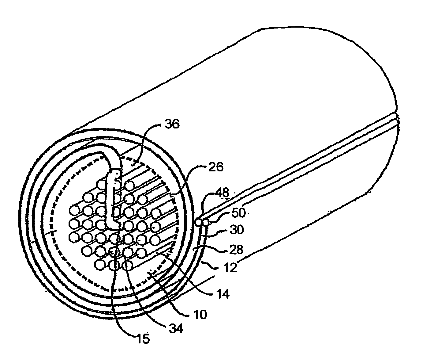
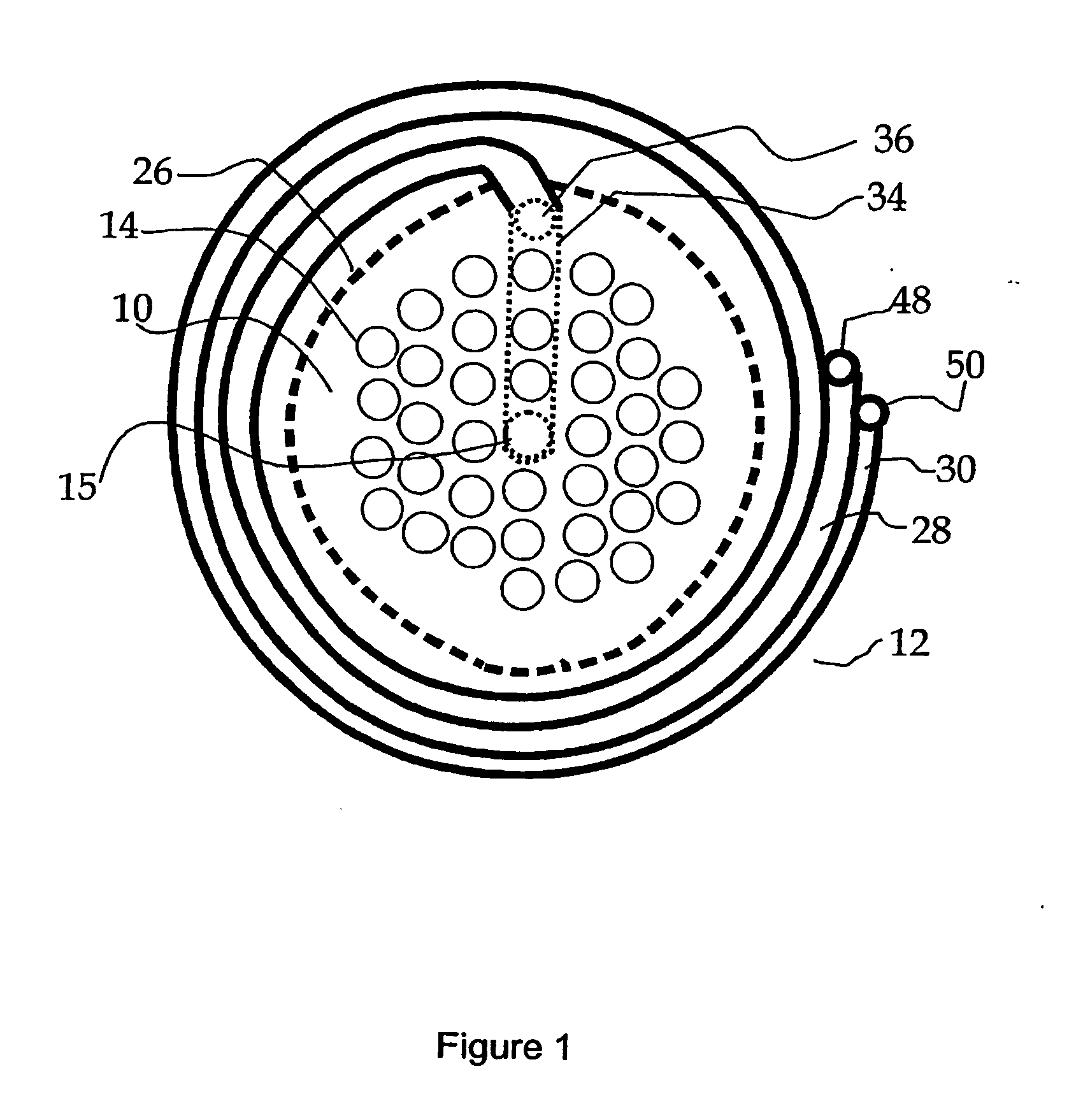
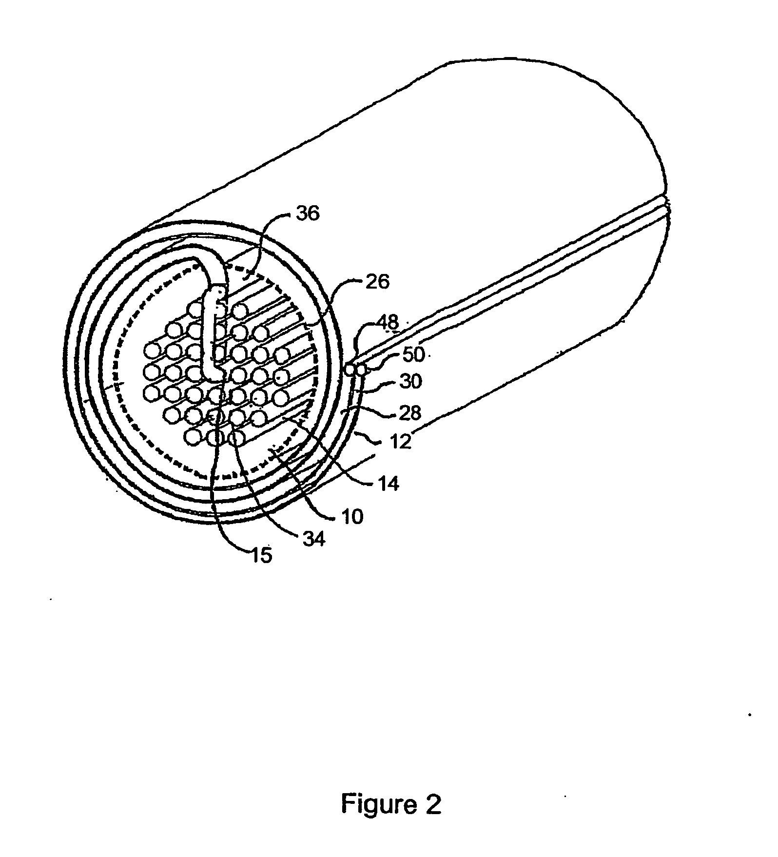
[0008] It is an general object of the invention to provide effective thermal management of a fuel cell stack, and in particular, to effectively heat reactant gases using the heat created during electricity generation in the stack. It is a specific objective of the invention to provide a heat exchanger for a fuel cell stack that effectively transfers heat from exhaust reactant to supply reactant, provides thermal insulation to the stack, and is relatively cost-effective to manufacture.

Problems solved by technology

The large size of the Siemens Westinghouse fuel cells (typically >5 mm diameter) and the relatively low power density (power output per unit volume) of the stack design makes such a fuel cell stack impractical for small scale applications such as portable electronic devices.
One of the challenges for SOFC systems is efficient thermal management.
When a stack's size is reduced, the stack's ratio of outer surface area to volume tends to increase, which results in an increase in potential heat loss relative to rated power output.
Inadequate thermal management can result in significant amounts of generated heat to be lost, such that heat from an external source must be used to heat the incoming reactant streams as well as to keep the stack within its operating temperature range.
Such external heat sources constitutes a parasitic load on the SOFC system which reduces the operating efficiency of the system.
The manufacture of such heat exchangers and the integration of the fuel cell within the heat exchanger are laborious and not commercially practical for large scale manufacture.

Method used


Image

  • Heat exchanger for fuel cell stack
  • Heat exchanger for fuel cell stack
  • Heat exchanger for fuel cell stack

Examples


Embodiment Construction

[0026] When describing the present invention, the following terms have the following meanings, unless indicated otherwise. All terms not defined herein have their common art-recognized meanings. [0027] The term “ceramic” refers to inorganic non-metallic solid materials with a prevalent covalent or ionic bond including, but not limited to metallic oxides (such as oxides of aluminum, silicon, magnesium, zirconium, titanium, chromium, lanthanum, hafnium, yttrium and mixtures thereof) and nonoxide compounds including but not limited to carbides (such as of titanium tungsten, boron, silicon), suicides (such as molybdenum disicilicide), nitrides (such as of boron, aluminum, titanium, silicon) and borides (such as of tungsten, titanium, uranium) and mixtures thereof; spinels, titanates (such as barium titanate, lead titanate, lead zirconium titanates, strontium titanate, iron titanate), ceramic super conductors, zeolites, and ceramic solid ionic conductors (such as yittria stabilized zirco...


PUM

PropertyMeasurementUnit
diameteraaaaaaaaaa
temperaturesaaaaaaaaaa
diametersaaaaaaaaaa

Abstract

This invention relates to a fuel cell system comprising a fuel cell stack and a heat exchanger wrapped around the stack. The fuel cell stack comprises a fuel cell that operates at high elevated temperatures, such as a solid oxide fuel cell; the fuel cell can have a tubular configuration and comprise a pair of concentrically arranged electrode layers sandwiching a concentrically arranged electrolyte layer. The heat exchanger wraps around the fuel cell stack and comprises a flexible, thermally conductive first layer and an overlapping flexible, thermally conductive second layer spaced from the first layer. The first and second layers define adjacent annular oxidant supply and oxidant exhaust channels when wrapped around the stack. The exhaust channel is communicative with heated exhaust oxidant flowing from the stack, and the oxidant supply channel is communicative with supply oxidant that flows to the stack and is heated by heated exhaust oxidant in the adjacent oxidant exhaust channel and from heat radiating from the stack.

Description

FIELD OF THE INVENTION [0001] This invention relates generally to fuel cells, and in particular, to a heat exchanger for a fuel cell stack. BACKGROUND OF THE INVENTION [0002] There is a class of fuel cells that operate at high elevated temperatures. One type of such fuel cell is a solid oxide fuel cell (SOFC), which comprises two electrodes (anode and cathode) separated by a ceramic, solid-phase electrolyte. To achieve adequate ionic conductivity in such a ceramic electrolyte, the SOFC operates at elevated temperatures typically in the order of about 1000° C. The material in typical SOFC electrolytes is a fully dense (i.e. non-porous) yttria-stabilized zirconia (YSZ) which is an excellent conductor of negatively charged oxygen (oxide) ions at high temperatures. Typical SOFC anodes are made from a porous nickel / zirconia cermet while typical cathodes are made from magnesium doped lanthanum manganate (LaMnO3), or a strontium doped lanthanum manganate (also known as lanthanum strontium ...

Claims


Application Information

Patent Timeline
Patent Type & Authority Applications(United States)
IPC IPC(8): H01M8/04F28F7/00H01M8/04007F28D9/04F28D21/00H01M8/1213
CPCF28D9/04H01M8/04014H01M8/04074Y02E60/50H01M8/243H01M8/2475H01M8/0612H01M8/2485H01M8/2457
Inventor SARKAR, PARTHORHO, HONGSANGYAMARTE, LUISKOVACIK, GARY
Owner INNOTECH ALBERTA INC
Why Eureka
Try Eureka