[0039] The effect of the invention is particularly good, if the cover is formed by a covering which extends over the whole surface of the wafer to be annealed.
[0040] The wafer support unit preferably enables a pressure-free support of a single wafer per support unit, e.g., only with its dead load.
[0041] The bottom and / or the cover of the wafer support, preferably both the bottom and the cover, are preferably either completely or partially gas permeable, e.g., by an open-porous and particularly a microporous structure with open
porosity. Optionally, the bottom and / or cover are only partially gas permeable in a surface area facing to the wafer. The preferably gas permeable material of the bottom and / or the cover of the support preferably has a
high heat conductivity and a high flatness. Suitable gas permeable materials, for example, are
graphite, ceramics such as, e.g., Al2O3, and cermets, with an appropriate open
porosity. The gas permeability of the bottom and / or the cover of the wafer support unit is suitably 1.0 cm2 / s or lower, preferably 0.50 cm2 / s or lower, more preferably 0.10 cm2 / s or lower, and in particular 0.05 cm2 / s or lower (e.g. measured for air as a reference gas at
ambient pressure and ambient temperature according to DIN51935). The gas permeability and
porosity may be adjusted depending on the material used and the desired conditions (wafer material, annealing temperature, distance of the support bottom to the cover, etc.) by methods known to the person skilled in the art, wherein preferably the bottom and / or the cover of the wafer support should have open pores at least in the surface facing the wafer surface. The open porosity (measured e. g. according to DIN51918) of the porous material for the bottom and / or the cover of the wafer support may suitably be 20 vol. % or lower, preferably 15 vol. % or lower, and more preferably 10 vol. % or lower. It is also possible to make the wafer porous or gas permeable only in a portion of the bottom and / or the cover of the wafer support, which portion surrounds the inserted wafer, whereas the remaining portion is coated by a gas-impermeable material having a
high heat conductivity, such as
sapphire (Al2O3), SiO2-bonded ZrO2, or SiC. Good results have been achieved also with a SiC-coated
graphite cassette forming the bottom and the cover of the wafer support, which is gas-impermeable except for the region of a
diffusion barrier (described in further detail below), i.e., in the periphery where stacked cassettes of wafer support units contact each other. For the bottom and / or the cover of the wafer support, a material is preferred which is made by pressing
graphite. More preferably, the material is composed of ultrapure graphite particles, because of the particularly
high heat conductivity and high flatness achievable thereby. However, also suitable are other, preferably ultrapure materials or mixtures of different materials, which can be strongly pressed to a
residual porosity. Preferably, the cover is made of the same gas permeable, porous material as the support bottom. This may be realized, for example, in the embodiment of the cassette form described in more detail below.
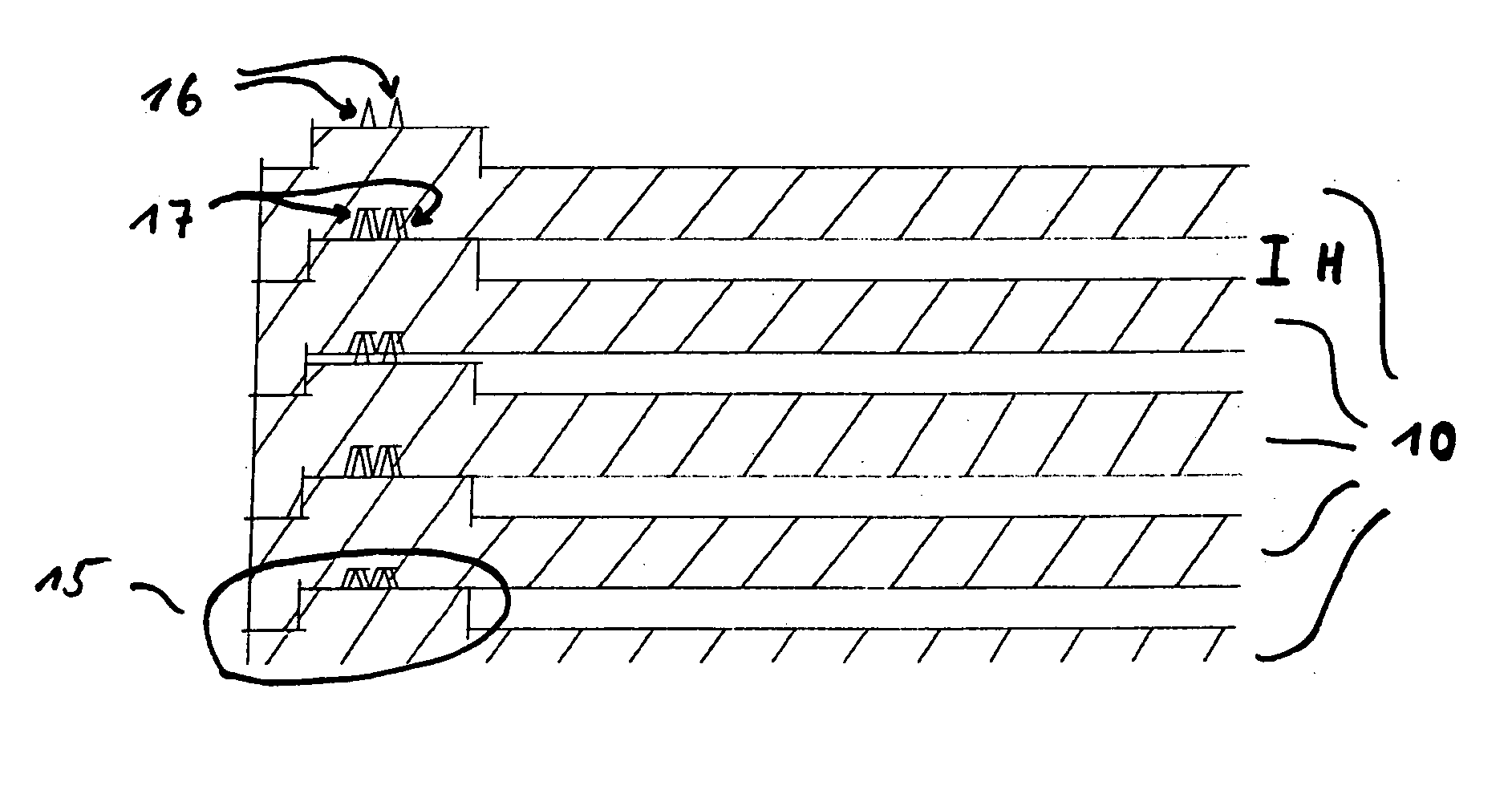
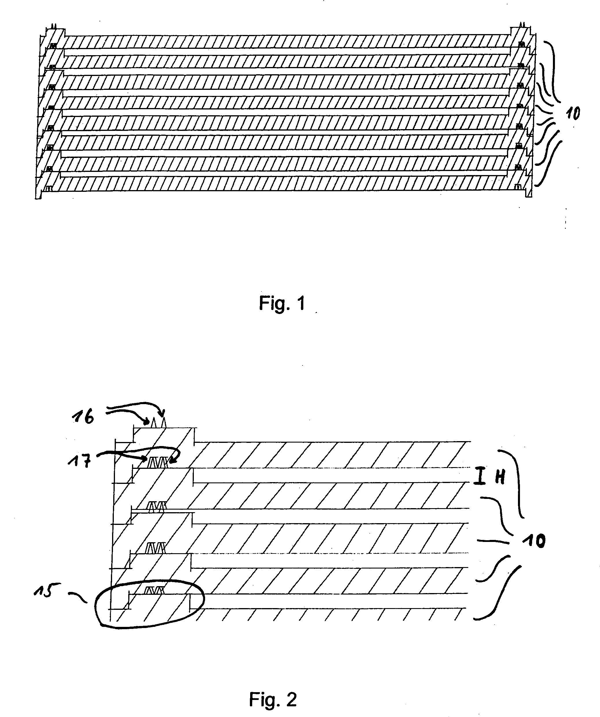
[0042] Providing a limited distance and / or optionally providing the pore structure defines a micro volume. The III-V semiconductor-comprising surface to be annealed is not encapsulated or covered by another material. Rather, this surface has contact to the aforementioned micro volume due to the limited distance to the cover and / or the porosity of the cover material. Thus, a (
mass) transport can take place between the III-V semiconductor material and the micro volume defined above the III-V semiconductor-comprising surface. In particular, it is possible that an advantageous transport and / or exchange of the V-component, such as, e.g., As or P, can take place. On the one hand, a degradation of the surfaces under the formation of Ga droplets is surely excluded, and on the other hand, wafers having enhanced use properties can thereby be prepared in a particular efficient manner. Both an improved surface quality is achieved, by decreasing the COPs, and the characteristic fracture strength of the annealed wafer is significantly improved. It is believed that a particularly good homogenization of the surface region of the annealed wafers is effected by means of the defined micro volume. The effect is particularly excellent, if the wafer support unit is defined in its dimensions such that the distance between the surface of the wafer to be supported and the cover or covering laid on top thereof is about 0.05-0.75 mm, further preferably about 0.2-0.5 mm and, in particular, about 0.3-0.4 mm, and forms a corresponding micro volume. For example, referring to a preferred, non-limiting, typical wafer thickness of about 0.5-1 mm, the distance between the bottom of the support and the cover of the corresponding wafer support unit is at least about 0.5 mm (i.e., in a gap-free
overlay of the cover on the wafer when using a 0.5 mm-thick wafer) and varies up to maximally about 3 mm (i.e., applying the maximum distance of the wafer to the cover of 2 mm, when using a 1 mm-thick wafer). The wafer support unit is further defined in its dimension such that, preferably, a volume
diameter is defined that is larger and in particular only slightly larger than the
diameter of the wafer to be treated, for example, corresponding to maximally 110%, preferably maximally 105%, or further preferably maximally 101% of the
diameter of the wafer to be treated.
[0043] In one particular preferred embodiment of the invention, the wafer support unit may form a limited, wafer-receiving space such that an unhindered
free gas access to the wafer surfaces is at least decreased and is preferably not possible. On the other hand, a hermetic sealing of the wafer in the support unit is not desirable. Therefore, there is preferably a certain minimum
gas exchange rate between the
atmosphere inside the micro volume and the
atmosphere outside the wafer support unit; however, the
gas exchange rate is substantially decreased in comparison with a
free gas exchange. The practical realization is typically accomplished by the provision of a gas permeability or open porosity as mentioned above, and / or by the provision of a further
diffusion barrier which will be described in further detail below.
[0044] The wafer support unit is preferably designed to allow a continuous, horizontally flat-extending support of the whole lower surface of the wafer. In order to make the support as uniform as possible, suitably no borings or openings are provided in the support bottom. The invention permits strains to be avoided which would occur in the annealing treatment by the influence of the
dead weight of the wafer, if supported neither horizontally nor continuously uniformly and in particular if supported at individual points, because the yield stress (which is temperature-dependent) is exceeded by the load gravity within the annealed material, resulting in the formation of dislocations and unacceptable slip lines. This influence is particularly pronounced in GaAs due to its comparatively
high density.

