
Device for producing extreme UV radiation

a radiation device and radiation technology, applied in the direction of photomechanical equipment, instruments, nuclear engineering, etc., can solve the problems of increasing production costs, shortening the maintenance and replacement period of the evacuation device of the euv radiation producing device, and reducing the evacuation performance of the evacuation device or similar

Active Publication Date: 2007-01-25
USHIO DENKI KK
View PDF2 Cites 33 Cited by
  • Summary
  • Abstract
  • Description
  • Claims
  • Application Information

AI Technical Summary

Benefits of technology

The invention is a device that produces extreme ultraviolet (EUV) radiation. The device has a chamber where a high-density plasma is formed and contains tin or a tin compound. The device prevents the gas released from the chamber from passing through the evacuation device connected to the chamber, which allows for the evacuated gas without any tin or tin compound to pass through. This separation between the chamber and the evacuation device allows for longer maintenance and replacement of the evacuation device. Additionally, the device can convert tin or tin compound into raw material for recycling and reuse.

Problems solved by technology

However there is also the disadvantage.
The tin, which exists in the evacuated gas and which is formed by decomposition of tin hydride and of a tin compound in the evacuated gas, adheres as solid tin to the rotor and the sliding part of the vacuum pump of the evacuation device; this leads to the disadvantage of a decrease of the evacuation performance of the evacuation device or to similar disadvantages.
Therefore, there is the disadvantage that, in an EUV radiation producing device using tin as the EUV radiating species, the period of the maintenance and the replacement period of the evacuation device of the EUV radiation producing device must be shorter than in an EUV radiation source using xenon as the EUV radiating species.
Since increase of the shutdown of the device due to maintenance, i.e., an increase in the mean time to repair, leads directly to an increase of production costs, there is a demand for reducing the shutdown of the device to a minimum.

Method used


Image

  • Device for producing extreme UV radiation
  • Device for producing extreme UV radiation
  • Device for producing extreme UV radiation

Examples


first embodiment

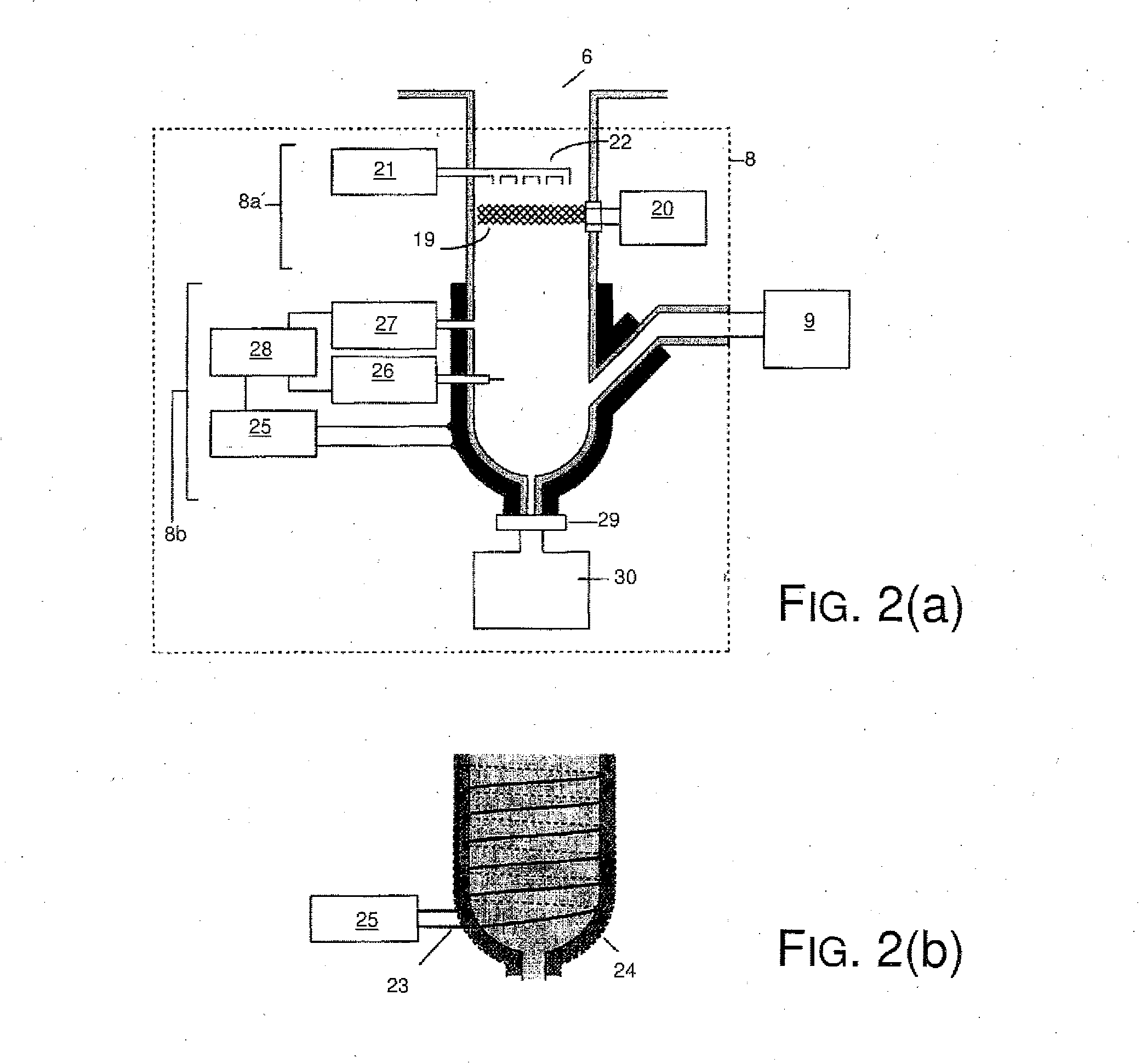
[0057]FIG. 2(a) is a cross section of the arrangement of the treatment unit 8. FIG. 2(b) is an outside view of the heating treatment part 8b of the treatment unit 8. Apparent from these figures, the treatment unit 8 comprises, for example, a steel tube and has an arrangement of two-stage treatment process to separate the tin and / or tin compound from the evacuated gas which contains tin and / or a tin compound.

[0058] First, on the side of the vacuum vessel (side of the second chamber 10b) of the treatment unit 8, there is a hydrogen radical treatment part 8a to convert tin and / or a tin compound in the evacuated gas into a hydride and to make it chemically stable stannane. In the hydrogen radical treatment part 8a, for example, there is a mesh texture tungsten filament 19 that extends across the flow path of the evacuated gas. A heating power supply 20 is connected to the tungsten filament 19. Furthermore, a hydrogen gas supply nozzle 22, which is connected to a hydrogen gas supply unit...

second embodiment

[0068]FIG. 3(a) is a cross section of the arrangement of the treatment unit 8 of the invention. FIG. 3(b) is a schematic view in which the heating structure 31, of FIG. 3(a) is shown by itself. FIG. 3(c) is a schematic view in which the heating structure 31 which is shown in FIG. 3(b) is viewed from above.

[0069] As these figures show, for the heating treatment part 8b for example in the steel tube as the evacuated gas passage, a heating structure 31 which built in a heating apparatus to the frame of stainless steel, ceramic or the like is arranged. The heating structure 31 is connected to the heating power supply 25. When power is supplied to the heating structure 31 from the heating power supply 25, the heating structure 31 is heated. The steel tube in the vicinity of the heating structure 31 is covered with a heat insulating material 24 so that heat does not dissipate.

[0070] The heating structure 31 is formed of numerous fins 31, 31a, 31b, 31c . . . which are designed to enlarge ...

fourth embodiment

[0083]FIG. 5(a) is a cross section of the arrangement of the treatment unit 8 of the invention. FIG. 5(b) is a schematic view in which the endothermic structure shown in FIG. 5(a) is shown by itself FIG. 5(c) is a schematic view in which the endothermic structure 31 shown in FIG. 5(b) is viewed from above. As these figures show, in the cooling treatment part 8c, for example, in the steel tube evacuated gas passage, there is an endothermic structure 36 in which there is a coolant circulation line path in a frame of copper, aluminum or the like.

[0084] A cooling device 32 is connected to the coolant circulation line path of the endothermic structure 36. By supplying a cooling medium from the cooling device 32, the endothermic structure 36 is cooled. The steel tube in the vicinity of the endothermic structure 36 is covered with a heat insulating material 24 to prevent the cooling air from being dissipated.

[0085] The endothermic structure 36 has fins 36a, 36b, 36c . . . which are design...


PUM


Abstract

An extreme UV radiation producing device in which adhesion of solid tin in the vacuum pump of an evacuation device is restricted, so that the maintenance period and the replacement period of the pump is prolonged is achieved by the provision of a treatment unit between a radiation source chamber and the evacuation device. The treatment device has a hydrogen radical producing part in which tin and / or a tin compound in the evacuated gas from the radiation source chamber is / are made into a tin hydride; and a heat treatment part in which the tin hydride is thermally decomposed and in which the tin produced liquefied and separated from the evacuated gas. The liquid tin is fed into a collecting / storage vessel and the evacuated gas from which the tin and / or a tin compound has been removed fed to the evacuation device.

Description

BACKGROUND OF THE INVENTION [0001] 1. Field of the Invention [0002] The invention relates to a device for producing extreme UV radiation which emits extreme UV radiation. The invention relates especially to a device for producing extreme UV radiation using tin as the radiation source of the extreme UV radiation in which the service life of the evacuation device and the like is prolonged by producing hydrogen radicals. [0003] 2. Description of Related Art [0004] An improvement in resolution has been required in projection exposure tool with miniaturization and increased integration of integrated semiconductor circuits for its manufacture. To meet these requirements, the wavelengths of the exposure radiation source are being increasingly shortened. As a semiconductor exposure radiation source of the next generation in succession to an excimer laser device, a device for producing extreme UV radiation (hereinafter also called an EUV radiation producing device) is being developed which e...

Claims


Application Information

Patent Timeline
Patent Type & Authority Applications(United States)
IPC IPC(8): G21G4/00
CPCB82Y10/00G21K2201/061H05G2/005H05G2/003G21K2201/064G03F7/70033
Inventor YABUTA, HIRONOBUSUMITOMO, TAKU
Owner USHIO DENKI KK
Learn More