Electrode including Si-containing material layer and porous film, and lithium battery employing the same

a lithium battery and porous film technology, applied in the direction of secondary cells servicing/maintenance, cell components, cell component details, etc., can solve the problems of low ohmic contact efficiency, high reactivity of lithium itself, and short circuit between electrodes, so as to improve ohmic contact efficiency and reduce contact angle , the effect of increasing the adhesion

Inactive Publication Date: 2007-01-25
SAMSUNG SDI CO LTD
View PDF12 Cites 21 Cited by
  • Summary
  • Abstract
  • Description
  • Claims
  • Application Information

AI Technical Summary

Benefits of technology

[0034] In the preferred embodiments of the present invention, when the Si-containing material layer is applied on the surface of the electrode current collector, the Si atom of the Si-containing material layer will react with an OH group on the surface of the electrode current collector to prevent oxidation of the electrode current collector so as to ensure the life cycle thereof and will serve to improve ohmic contacts so as to increase the adhesion between the electrode active material and the electrode current collector. Also, when the Si-containing material layer is applied on the electrode active material layer, the Si atom of the Si-containing material layer will react with an OH group on the negative electrode to remove the OH group, thus reducing the contact angle between the electrolyte and the negative electrode active material. This increases the wettability of the electrolyte, thus enhancing the permeability thereof

Problems solved by technology

However, when a lithium metal is used in a negative electrode, a lot of dendrites grow on the lithium surface when charged, leading to a reduction in charge / discharge efficiency and short-circuits between the electrodes.
Another problem is the instability (high reactivity) of lithium itself.
In these studies, expansion or shrinkage caused by charge / discharge is reduced compared to the case of using the lithium or lithium alloy, but there are problems in that capacity is reduced and initial charge / discharge efficiency is lowered, compared to the case of using lithium.
However, the structure, in which the electrode active materials are in direct contact with the electrode current collector, has problems in that, due to a difference in the ohmic contacts between a portion, in which the electrode active materials are in contact with the electrode current collector, and another portion, in which the electrode active materials are not in contact with the electrode current collector, a difference in the concentration of electron density occurs, so that the ionization of the electrode current collector progresses, and thus the resistance of the battery increases due to the oxidation of metal, and the ionization easily occurs even at low voltage.
Also, it has a problem in that, at a portion in which an electric field line is not concentrated, ions of the electrode current collector are deposited as metals, causing dendritic phenomena.
When the flow of lithium ions stops, the current flow between the internal and external portions of the battery becomes blocked, thereby slowing or stopping the temperature increase in the battery.
However, in a high-capacitance secondary battery, a large amount of current can flow over a short period of time.
When excessive current flows in such a battery, the temperature in the battery cannot be decreased by shutting down the pores of the separator and blocking current flow.
Furthermore, the heat generated by such excessive current flow may cause the separator to continue to melt and destruct.
As a result, a short circuit due to the destruction of the separator becomes increasingly possible.

Method used


Image

  • Electrode including Si-containing material layer and porous film, and lithium battery employing the same
  • Electrode including Si-containing material layer and porous film, and lithium battery employing the same
  • Electrode including Si-containing material layer and porous film, and lithium battery employing the same

Examples


example 1

[0105] 50 g of a poly(vinylidene fluoride (PVDF) binder and 1000 g of graphite having an average diameter of 20 μm were added to 700 g of a n-methyl-pyrrolidone (NMP) solvent, and then stirred using a mechanical stirrer for about 30 minutes to prepare a negative active material slurry. The slurry was applied on a copper current collector to a thickness of about 150 μm, and dried and then further dried at 150° C. in a vacuum. Then, to form a porous film, sintered particles obtained by heating zirconium oxide at 900° C. for about 10 minutes were mixed with 95 g of the binder and 5 g of modified soluble acrylonitrile rubber (BM-720H, Zeon Co., Ltd., Japan) at a weight ratio of zirconium oxide: binder of 95:5 in 150 ml of a solvent to make a liquid mixture. The electrode plate was immersed in the liquid mixture, and the thickness of the film formed on the plate was controlled to 20 μm using a gravure roller. Then, the film was dried at 120° C., and thermally treated at 150° C. for the p...

example 2

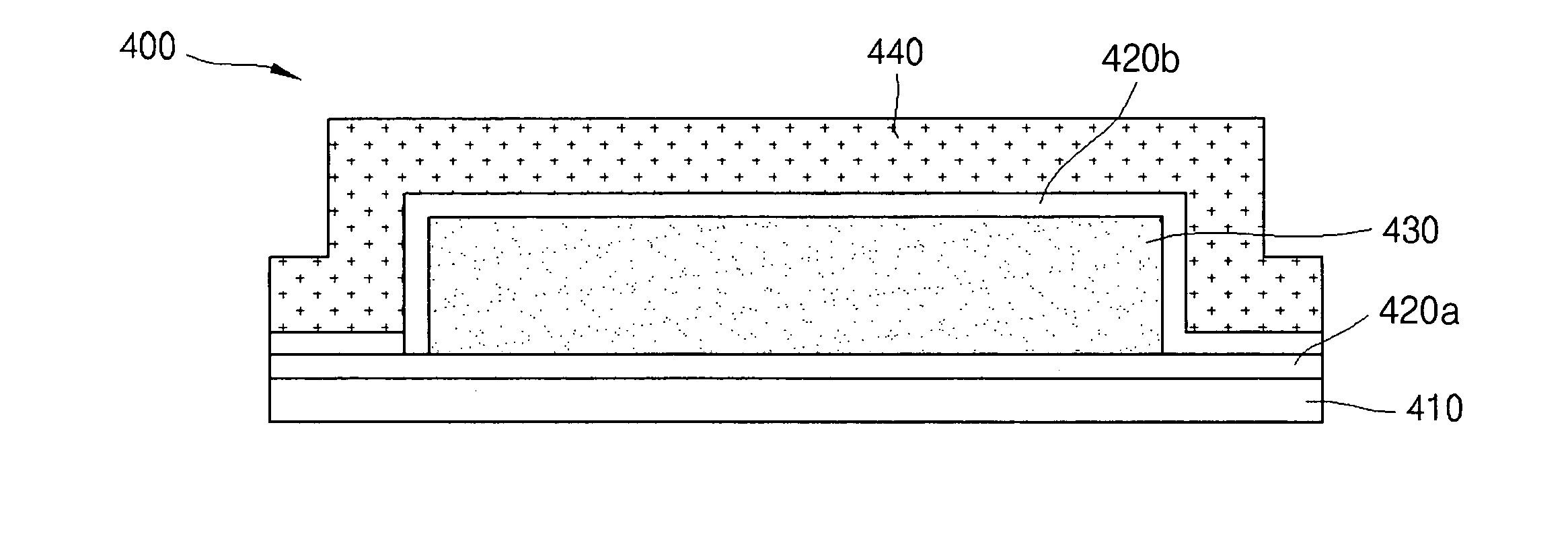
[0106] HMDS (OAP, Tokyo Ohka Kogyo Co. Ltd) was formed on a copper (Cu) current collector to a thickness of 0.005 μm by vapor phase deposition. Then, 50 g of a PVDF binder and 1000 g of graphite having an average diameter of 20 μm was added to 700 g of a NMP solvent and stirred using a mechanical stirrer for 30 minutes to prepare a negative electrode active material slurry. Then, the slurry was applied on the copper current collector to a thickness of about 150 μm, and dried and then further dried at 150° C. in a vacuum. Then, to form a porous film, sintered particles obtained by heating zirconium oxide 900° C. for about 10 minutes were mixed with 95 g of a binder and 5 g of modified soluble acrylonitrile rubber (BM-720H, Zeon Co., Ltd., Japan) at a weight ratio of zirconium oxide: binder of 95:5 in 150 ml of a solvent to make a liquid mixture. The electrode plate was immersed in the liquid mixture, and the thickness of the film formed on the plate was controlled to 20 μm using a gr...

example 3

[0107] 50 g of a PVDF binder and 1000 g of graphite having an average diameter of 20 μm was added to 700 g of a NMP solvent and then stirred using a mechanical stir for 30 minutes to prepare a negative electrode active material slurry. The slurry was applied on a copper current collector to a thickness of about 150 μm, and dried and then further dried at 150° C. in a vacuum. Then, HMDS (OAP, Tokyo Ohka Kogyo Co. Ltd) was formed on the copper (Cu) current collector to a thickness of 0.005 μm by vapor phase deposition. Then, to form a porous film, sintered particles obtained by heating zirconium oxide 900° C. for about 10 minutes were mixed with 95 g of a binder and 5 g of modified soluble acrylonitrile rubber (BM-720H, Zeon Co., Ltd., Japan) at a weight ratio of zirconium oxide: binder of 95:5 in 150 ml of a solvent to make a liquid mixture. The electrode plate was immersed in the liquid mixture, and the thickness of the film formed on the plate was controlled to 20 μm using a gravur...


PUM

PropertyMeasurementUnit
thicknessaaaaaaaaaa
thicknessaaaaaaaaaa
temperaturesaaaaaaaaaa

Abstract

An electrode which has a Si-containing material layer and a porous film, and a lithium battery employing the same. In the electrode, the Si-containing material layer is applied on an electrode current collector and/or an electrode active material to protect the surface of the electrode current collector from oxidation. Also, the applied Si-containing material layer enhances the adhesion between the electrode current collector and the electrode active material to improve cycle life characteristics. Also, it increases the adhesion between the electrode active material and the porous film to reduce resistance, and to improve ohmic contacts and to lower the Shottkey barrier. In addition, the electrode includes the porous film functioning as a separator, and thus can provide a battery which is safe under conditions of overcharge and heat exposure without needing an additional separator.

Description

CROSS-REFERENCE TO RELATED APPLICATIONS AND CLAIM OF PRIORITY [0001] This application claims priority to and the benefit of Korean Patent Application No. 10-2005-0066867 filed on Jul. 22, 2005 in the Korean Intellectual Property Office, the entire contents of which are incorporated herein by reference. BACKGROUND OF THE INVENTION [0002] 1. Field of the Invention [0003] The present invention relates to an electrode including a Si-containing material layer and a porous layer, and a lithium battery employing the same, and more particularly to an electrode, in which a Si-containing material is applied on an electrode current collector and / or an electrode active material, to protect the surface of the electrode current collector from oxidation, and to enhance the adhesion between the electrode current collector and the electrode active material, leading to improvement in cycle life characteristics, and to increase the adhesion between the electrode active material and the porous film, th...

Claims


Application Information

Patent Timeline
Patent Type & Authority Applications(United States)
IPC IPC(8): H01M4/66H01M2/16H01M4/02H01M4/133H01M4/139
CPCH01M2/166H01M2/1673H01M4/133H01M4/139H01M4/62H01M4/66H01M2/168H01M10/4235H01M10/52H01M2004/027Y02E60/12Y02E60/50H01M4/667H01M50/446H01M50/46Y02E60/10H01M4/134H01M10/0525H01M50/461
Inventor KIM, JIN-HEEHAN, WON-CHULLMIN, JAE-YUN
Owner SAMSUNG SDI CO LTD
Why Eureka
Try Eureka