Vinyl polymer photoconductive elements

a polymer and photoconductive element technology, applied in the field of electrotrophotography, can solve the problems of irregular image defect, and affecting the quality of images produced with photoconductive elements, and achieve good resistance to injection, thick and uniform, and resist the effect of hole transpor

Inactive Publication Date: 2007-02-01
EASTMAN KODAK CO
View PDF9 Cites 96 Cited by
  • Summary
  • Abstract
  • Description
  • Claims
  • Application Information

AI Technical Summary

Benefits of technology

[0031] The invention provides for a negatively chargeable photoconductive element having a p-type photoconductor, and including an electrical barrier polymer that has good resistance to the injection of positive charges, can be sufficiently thick and uniform that minor surface irregularities do not substantially alter the field strength, and resists hole transport over a wide humidity range. The barrier polymer is prepa

Problems solved by technology

As a consequence, irregularities in the coating surface, such as bumps or skips, can alter the electric field across the surface.
This in turn can cause irregularities in the quality of images produced with the photoconductive element.
One such image defect is caused by dielectric breakdowns due to film surface irregularities and/or non-uniform thickness.
The known barrier layer materials have certain drawbacks, especially when used with negatively charged elements having p-type charge transport layers.
Many known barrier layer materials are not sufficiently resistant to the injection of positive charges from the conductive support of the photoconductive element.
Thus, at low RH levels the ability to transport charge in such materials decreases and negatively impacts film electrical properties.
In all cases, care must be taken not to disrupt the layer with subsequent layers that are coated from solvents, as this may result in swelling of the electron transport layer, mixing with the layer, or dissolution of part or all of the polymer.
Furthermore, salts can make the layer subject to unwanted ionic transport.
Thus there is a need for polymers with planar, electron-deficient tetracarbonylbisimide groups and do not contain salts that can be coated from solvents, but will not be soluble or miscible with subsequent solvents or layers.
Further, there is a need for polymers with planar, electron-deficient tetracarbonylbisimide groups and do not contain salts that can b

Method used


Image

  • Vinyl polymer photoconductive elements
  • Vinyl polymer photoconductive elements
  • Vinyl polymer photoconductive elements

Examples


example 1

[0137] A photoconductive element is prepared substantially as described in Comparative Example 1, except that the barrier layer polymer is Polymer 1. The barrier layer solution is prepared at 10 wt % in tetrahydrofuran. The crosslinking agent and catalyst amounts were added as shown below in Table 1.

TABLE 1Formulation of Polymer 1Amilan ™Lot no.SolidsControlFormulation 1Amilan ™Amilan ™30 gCM8000Polymer 10.917%11.004 g Trixene BI 79630.080% 0.96 gK-kot Xc-C2270.003%0.036 gTOTAL WEIGHT30 g12SurfactantSF102310 drops

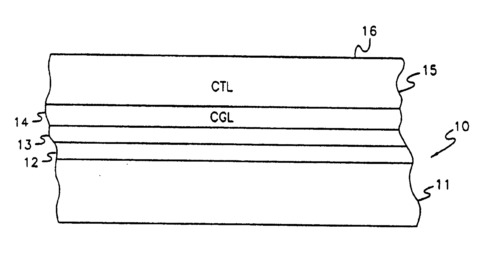
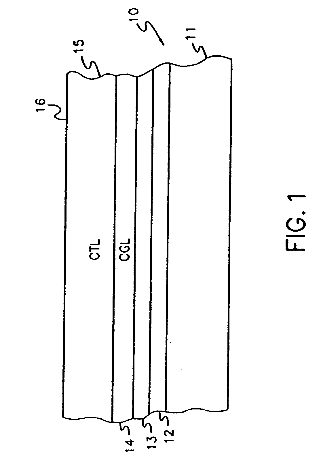
[0138] Trixene BI 7963 and K-kot Xc-C227 were obtained from Baxenden Chemicals Limited, Paragon Works, Baxenden, Nr. Accrington, Lancashire. BB5 2SL, United Kingdom. The Polymer 1 layer was web coated at a dry coverage of 0.05, 0.10, 0.20, and 0.30 g / ft2, the Amilan™ layer at 0.05 g / ft2. The samples were cured at 135° C. for 24 hours. They were overcoated with CGL and CTL as described in Comparative Example 1.

Evaluation

[0139] The films are tested in a laboratory appara...

example 2

[0141] A photoconductive element is prepared from Polymer 2 for use in dip coating. The barrier layer solution is prepared at 10 wt % in toluene. The crosslinking agent and catalyst amounts were added as shown in Table 3. An Amilan™ control prepared by web coating as described in Comparative Example 1 was overcoated in the same way as Polymer 2.

TABLE 3Formulation of Polymer 2ComponentWeight (g)Polymer 226.7Trixene BI 79633K-kot Xc-C2270.3Toluene270

[0142] The toluene solution contained 10 wt % solids of a total solution weight of 300 g or a total solution volume of 344 mL.

[0143] Nickel coated polyethylene terephthalate (7 mil) was dip coated into the solution of Polymer 2 and cured at 130° C. for 1 hour to give a dry layer of 0.65 microns. The polymer film was dipped a second time in the Polymer 2 solution to give a dry layer of 1.4 microns after curing. The process was repeated a third time to produce a total film thickness of 2 microns.

[0144] The barrier layers were dipped into...

example 3

Extraction of Naphthalenebisimide from Crosslinked Coatings

[0146] A photoconductive element is prepared from Polymer 3 for use in dip coating. The barrier layer solution is prepared at 10 wt % in tetrahydrofuran. The crosslinking agent and catalyst amounts were added as shown in Table 5. An Amilan™ control prepared by web coating as described in Comparative Example 1 was overcoated in the same way as Polymer 3.

TABLE 5Formulation of Polymer 3ComponentWeight (g)Polymer 324.92Trixene BI 79632.8K-kot Xc-C2270.28THF252

[0147] The tetrahydrofuran (THF) solution contained 10 wt % solids of a total solution weight of 280 g or a total solution volume of 249 mL.

[0148] Dip coatings of Polymer 3 were prepared in the same manner as for Polymer 2 except the substrate was either nickel or nickel overcoated with a 1 micron thick tin oxide / polyurethane smoothing layer. The total thickness after 3 dips was 1.7 microns.

[0149] The efficiency of crosslinking was examined by curing the samples for 1,...


PUM


Abstract

The present invention is a photoconductive element that includes an electrically conductive support, an electrical barrier layer disposed over said electrically conductive support, and disposed over said barrier layer, a charge generation layer capable of generating positive charge carriers when exposed to actinic radiation. The barrier layer includes a vinyl polymer with aromatic tetracarbonylbisimide side groups and crosslinking sites.

Description

FIELD OF THE INVENTION [0001] This invention relates to electrophotography. More particularly, it relates to polymers comprising a tetracarbonylbisimide group and to photoconductive elements that contain an electrical charge barrier layer comprised of said polymers. BACKGROUND OF THE INVENTION [0002] Photoconductive elements useful, for example, in electrophotographic copiers and printers are composed of a conducting support having a photoconductive layer that is insulating in the dark but becomes conductive upon exposure to actinic radiation. To form images, the surface of the element is electrostatically and uniformly charged in the dark and then exposed to a pattern of actinic radiation. In areas where the photoconductive layer is irradiated, mobile charge carriers are generated which migrate to the surface and dissipate the surface charge. This leaves in non-irradiated areas a charge pattern known as a latent electrostatic image. The latent image can be developed, either on the ...

Claims


Application Information

Patent Timeline
IPC IPC(8): G03G5/14
CPCG03G5/102G03G5/144G03G5/142
Inventor FERRAR, WAYNE T.JIN, XINWEISS, DAVID S.MOLAIRE, MICHEL F.GRUENBAUM, WILLIAM T.
Owner EASTMAN KODAK CO
Why Eureka
Try Eureka