Methods for fabricating nano and microparticles for drug delivery

a nano-particle and nano-particle technology, applied in the field of nano-particle fabrication methods for drug delivery, can solve the problems of lack of correlation between in vitro observations and in vivo performance of diffusion/degradation controlled devices, and inability to accurately predict drug diffusion/releas

Active Publication Date: 2007-02-08
BOARD OF RGT THE UNIV OF TEXAS SYST
View PDF5 Cites 56 Cited by
  • Summary
  • Abstract
  • Description
  • Claims
  • Application Information

AI Technical Summary

Problems solved by technology

Although progress has been made and several new products are coming in the market that can significantly enhance patient compliance, reduce side effects, and improve the quality of life, there remain several limitations of these approaches.
First, despite the development of sophisticated and sensitive assays to study drug release and polymer degradation in vitro, little correlation exists between in vitro observations and in vivo performance of diffusion / degradation controlled devices.
The effects of tissue environments in vivo, especially tissue pH, enzymes, salt concentrations, and the rarity with which perfect sink conditions are met, makes most prediction of drug diffusion / release inherently inaccurate.
Second, delivery systems that rely on particle-based strategies, e.g., micro and nanoparticles for tissue targeted delivery, suffer from the limitation that the bottom-up synthesis processes produce a large polydisperse population of particles whose physico-chemcial characteristics, drug release profiles, degradation kinetics, and material properties become hard to evaluate and reproduce, especially at pharmaceutical scales.
Third, the lack of a stimuli-responsive release mechanism results in the release of the drug in a somewhat uncontrolled manner, which often results in systemic side effects.
Fourth, particle-based drug carriers rely on emulsion or micelle formation for synthesis and drug loading, thereby achieving only limited and often poor encapsulation efficiency.
This limitation becomes particularly critical of highly expensive and difficult to synthesize drugs, leading to limited application and high cost.
Fifth, combining multiple functionalities (i.e., both targeting as well as stimuli-sensitive properties), in a controlled and reproducible manner is significantly difficult in self-assembled carrier systems.
However, such designs do not allow for simultaneous delivery of multiple agents (drugs, contrast agents etc.) and are yet to have demonstrated conclusive clinical efficacy.
A key issue in drug delivery is disease-responsive release.
Despite current efforts to target drug nanoparticles and liposomal drug carriers to diseased cells in vivo (Kreuter, J. Nanosci. Nanotechnol. 2004, 4:484-8; Park et al., Adv. Pharmacol. 1997, 40:399-435; Park et al., Semin. Oncol. 2004, 31:196-205; Noble et al., Expert Opin. Ther. Targets 2004, 8:335-53), it is inevitable that during transport to target cells and the extracellular residence time, significant amounts of toxic drugs will diffuse to normal tissues.
Control Release 2002, 78:165-73), the inherent complexity of bottom-up (i.e. self-assembly) synthetic approaches (e.g., emulsions or micelles) makes it difficult to incorporate both these functionalities in a single delivery platform.
Despite these efforts, major limitations in the drug delivery devices remain.
First, these devices are too large (>50 μm) to be injected in blood.
Second, they do not have any sensing mechanism to be physiologically responsive.
Significant technological challenges exist in fabricating such small carriers along with disease-responsive features using a purely top-down approach.

Method used


Image

  • Methods for fabricating nano and microparticles for drug delivery
  • Methods for fabricating nano and microparticles for drug delivery
  • Methods for fabricating nano and microparticles for drug delivery

Examples


example 1

Incorporation of the Peptide GFLGK in a Photocrosslinkable PEG Polymer

[0063] The peptide sequence GFLGK (molecular weight (MW) 527 Daltons, synthesized at ICMB Protein Facility at the University of Texas at Austin) was reacted with acrylate-PEG-N-Hydroxy-succinamide (ACRL-PEG-NHS, MW 3,400, Nektar Therapeutics, AL). The primary (alpha) amine of Glycine (G) and the primary amine of Lysine (K) at either end of a peptide molecule reacts with the N-Hydroxy-succinamide (NHS) groups of two hetero-bifunctional PEG chains, i.e., each peptide molecule crosslinks two PEG molecules. This creates a 2:1 molar reaction (ACRL-PEG-NHS: GFLGK) to form ACRL-PEG-GFLGK-PEG-ACRL (a homobifunctional PEG diacrylate). Specifically, the peptide was dissolved to a final concentration of 1 mg / mL in 50 mM sodium bicarbonate buffer, pH 8.2. Separately, the ACRL-PEG-NHS was also dissolved in 50 mM sodium bicarbonate buffer, pH 8.2. The PEG solution (300 μL) was then added one drop at a time into the peptide sol...

example 2

Fabrication Using Nanoimprint Lithography Technique

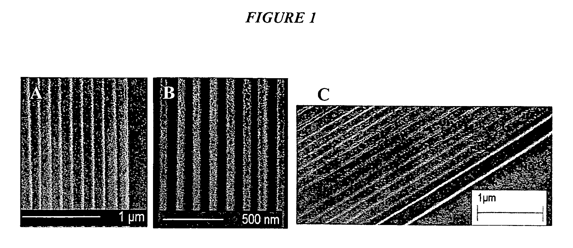
[0069] We employed the S-FIL nanoprint process (discussed supra) to imprint nanopatterns on polymers. In addition to the S-FIL method, we employed a thermal nanoprint process to imprint nanopatterns on a variety of other polymers including PMMA, BCB, hydrogensilsesquioxane (HSQ) and the electron beam resist ZEP 520A (FIG. 1). In this thermal nanoimprint process, the polymer film was heated to a temperature slightly higher than the glass transition temperature. The imprint template was treated with a release layer (such as Hexadecanethiol or Octanethiol for a GaAs imprint template) to facilitate the separation of the template from the polymer layer upon cooling. Because the polymer does not need to be photo-linkable, the thermal nanoimprint process can be used to pattern a wide variety of polymers.

example 3

Fabrication of Templates for Thermal Nanoimprinting of Drug Delivery Lidded Particles

[0070]FIG. 4 shows a schematic for the nanoimprint fabrication process of lidded particles as shown in FIG. 5, infra. Two reusable quartz templates for nanoimprinting are fabricated as described.

[0071] To make an example particle for use as a monodisperse drug carrier, we fabricated both silicon and quartz imprint templates using electron-beam lithography (EBL) combined with reactive ion etching (RIE) following an established procedure (Bailey et al., 2002, supra). Four inch p-type silicon test wafers were pre-cleaned with Pirhana. The wafers were then pre-baked (180° C., 30 s), spin coated with ZEP520 (3000 rpm for 60 sec.), and finally soft-baked (180° C., 30 sec.). Next the wafers were patterned using e-beam lithography (JEOL JBX-6000FS / E) with the following process parameters: EOS mode 7, 50 kV, 100 pA, exposure level / dose: 20 to −20. Between each step the wafers were developed with ZED n50 (...


PUM

PropertyMeasurementUnit
sizeaaaaaaaaaa
sizeaaaaaaaaaa
sizeaaaaaaaaaa

Abstract

The present invention generally relates to stimuli-responsive drug carriers and methods for making. More specifically, the present invention relates to stimuli-responsive lidded particles that respond to a physiological stimulus and dissolve at a target site inside the body thereby releasing therapeutic agents. The present invention further relates to solid, drug-loaded particles that are made from biodegradable polymers. The present invention further relates to methods for fabricating lidded particles and particles for drug delivery.

Description

PRIORITY CLAIM [0001] This application claims priority to U.S. Provisional Applications Nos. 60 / 678,639 filed May 6, 2005 and 60 / 719,844 filed Sep. 23, 2005, the contents of which are incorporated in their entireties herein.BACKGROUND OF THE INVENTION [0002] Therapeutic and diagnostic applications of nanofabrication technology are gaining increasing interest. Over the past several decades almost all efforts in controlled release drug delivery has been focused on polymer-based, diffusion / degradation-controlled delivery strategies. Current “controlled release” drug delivery systems are based primarily on particles or matrices of various polymers and lipids where the release of the therapeutic agent is controlled primarily by diffusion and hydrolytic degradation. Although progress has been made and several new products are coming in the market that can significantly enhance patient compliance, reduce side effects, and improve the quality of life, there remain several limitations of the...

Claims


Application Information

Patent Timeline
Patent Type & Authority Applications(United States)
IPC IPC(8): A61K9/50A61K9/16
CPCA61K9/5146A61K41/0042B82Y5/00G03F7/0002B82Y30/00B82Y40/00B82Y10/00
Inventor ROY, KRISHNENDUSHI, LIGLANGCHAI, LUZ CRISTAL S.
Owner BOARD OF RGT THE UNIV OF TEXAS SYST
Why Eureka
Try Eureka