Methods for performing microfluidic sampling

Inactive Publication Date: 2007-02-15
DUKE UNIV
View PDF25 Cites 123 Cited by
  • Summary
  • Abstract
  • Description
  • Claims
  • Application Information

AI Technical Summary

Benefits of technology

[0021] 4. Mixing-ratio control using programming operations, yielding better controllability and higher accuracy in mixing ratios.
[0022] 5. High throughput capability, p

Problems solved by technology

Because the sensors lie in a common channel, crosstalk or contamination between sensors is often a concern.
Additionally, mixing in microfluidic flows is usually quite challenging.
Sufficient time and distance must be provided for mixing, which places constraints on chip design and system flow rates.
A common limitation among all continuous-flow systems is that fluid transport is physically confined to permanently etched structures, and additional mechanisms are required to enhance mixing.
This in turn requires the use of valves and complex channeling, consuming valuable real estate on a chip.
In the microscopic world, effective mixing is a technical problem because it is difficult to generate turbulent flow by mechanical actuation.
Thus, mixing that depends on diffusion through limited interfacial areas is a limitation.
This causes chaotic rearrangement of fluid particles, and thus the mi

Method used


Image

  • Methods for performing microfluidic sampling
  • Methods for performing microfluidic sampling
  • Methods for performing microfluidic sampling

Examples


Example

EXAMPLE

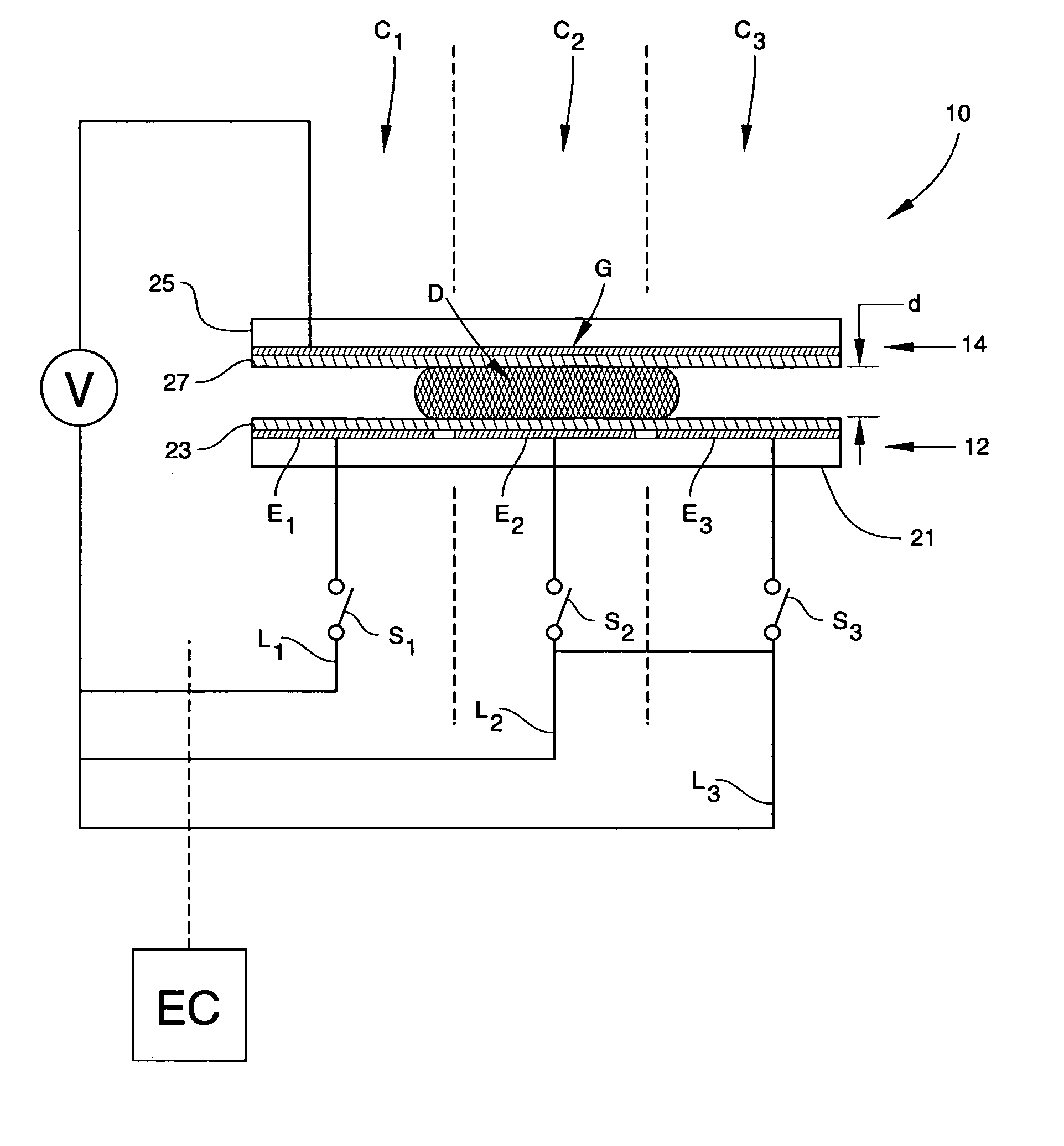
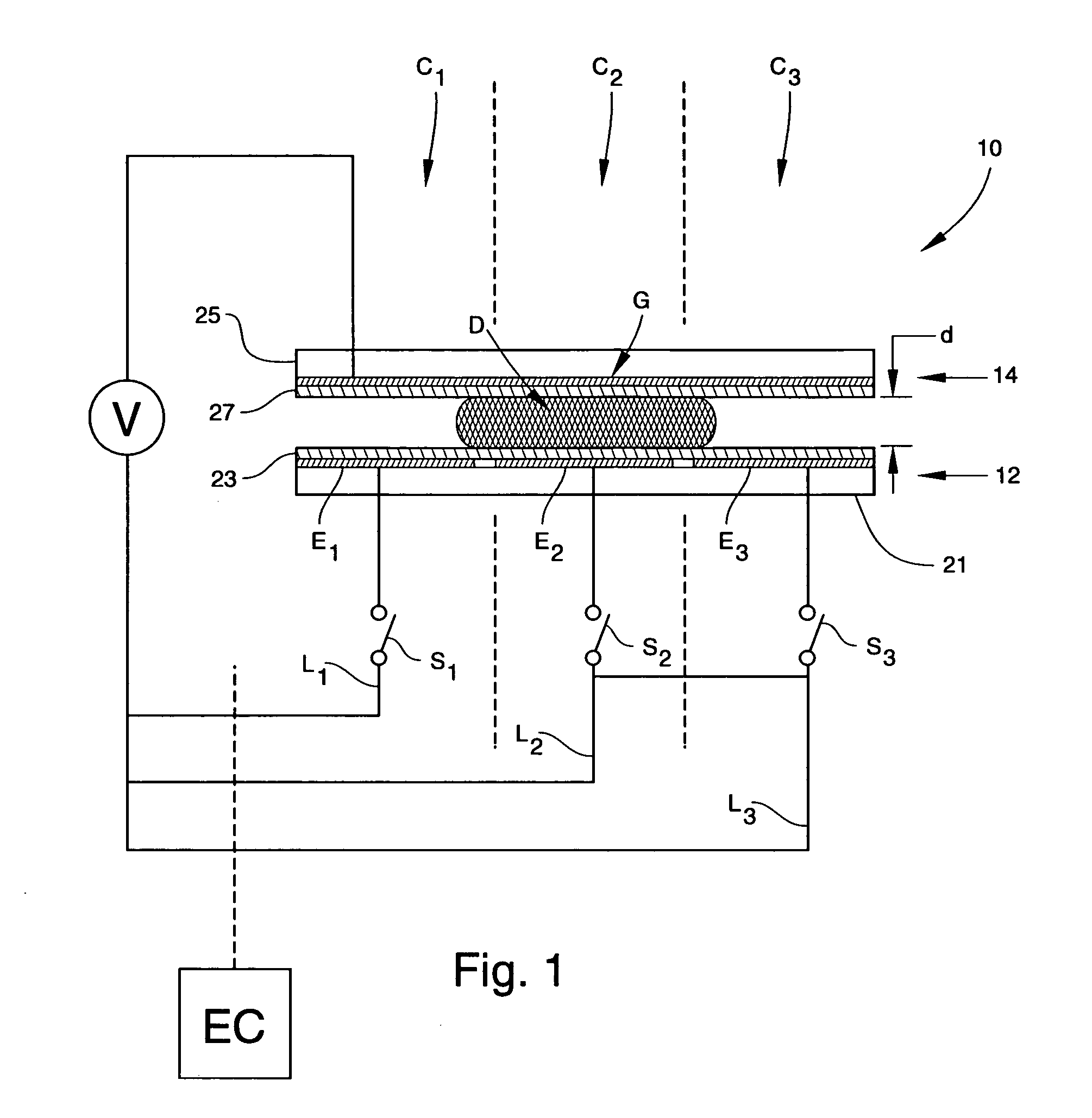
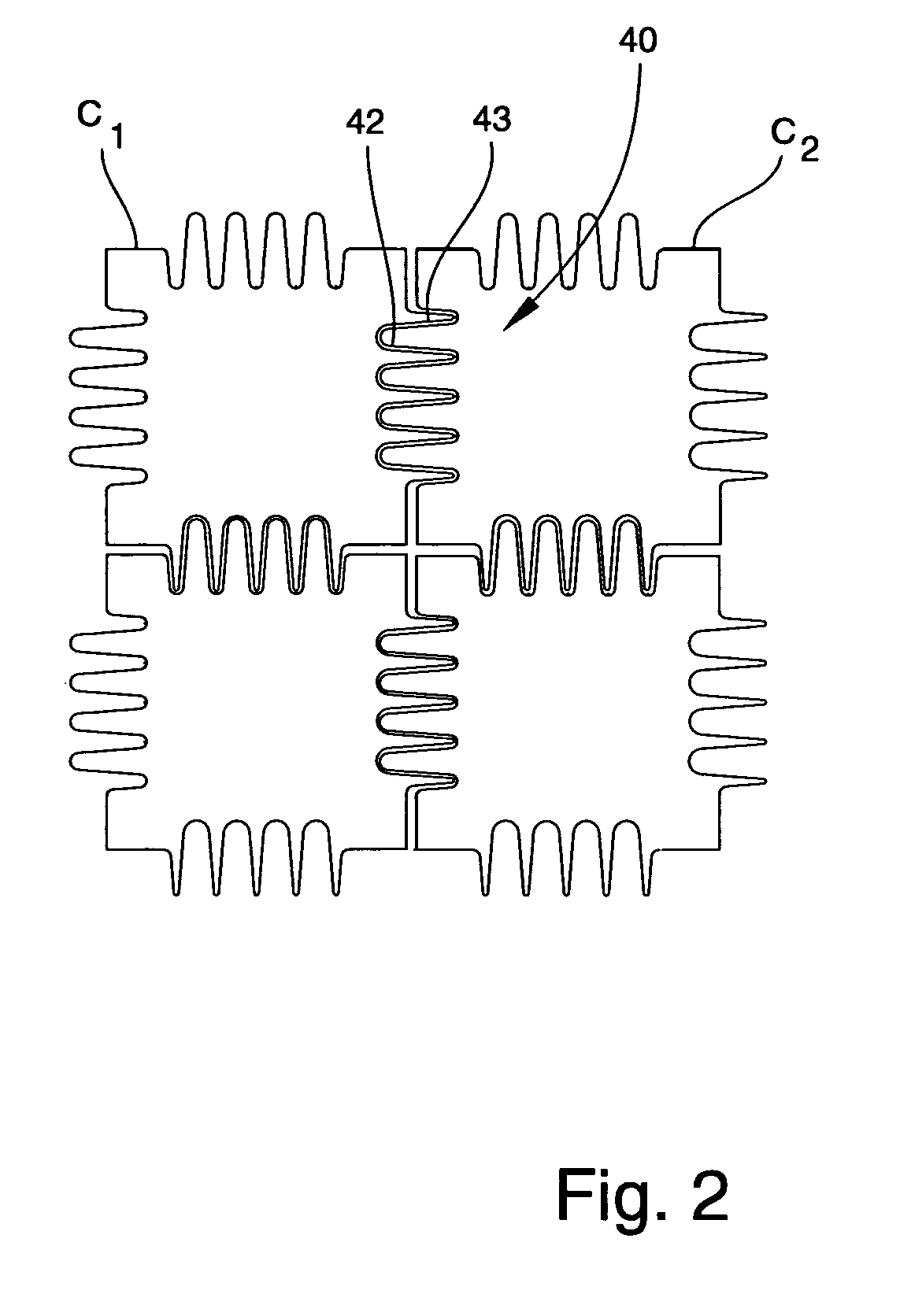
[0092] A prototype device consisting of a single linear array of seven interdigitated control electrodes E at a pitch of 1.5 mm was fabricated and tested. Control electrodes E were formed by patterning a 2000-Å thick layer of chrome on a glass lower plate 21 using standard microfabrication techniques. The chips were then coated with a 7000 Å layer of Parylene C followed by a layer 23 of approximately 2000 Å of TEFLON® AF 1600. Ground electrode G consisted of an upper plate 25 of glass coated with a conducting layer (Rζ<20 Ω / square) of transparent indium-tin-oxide (ITO). A thin (˜500 Å) layer 27 of TEFLON® AF 1600 was also applied to ground electrode G. The thin TEFLON® coating on ground electrode G served to hydrophobize the surface, but was not presumed to be insulative. After coating with TEFLON®, both surfaces had a contact angle of 104° with water.

[0093] Water droplets (0.7-1.0 μl) of 100 mM KCl were dispensed onto the array using a pipette, and upper plate 25 was posit...


PUM

PropertyMeasurementUnit
Flow rateaaaaaaaaaa
Electric potential / voltageaaaaaaaaaa
Areaaaaaaaaaaa

Abstract

Methods for performing microfluidic sampling are provided. The method includes providing a substrate including an arrangement of first, second and third electrodes, wherein the second electrode is interposed between the first and third electrodes. The method additionally includes causing a fluid input to continuously flow to the first electrode and biasing the first, second and third electrodes to a first voltage to cause a portion of the fluid input to spread across the second and third electrodes. The method further includes biasing the second electrode to a second voltage different from the first voltage to form a droplet on the third electrode, the droplet being separate from the fluid input.

Description

RELATED APPLICATIONS [0001] This application is a divisional of co-pending U.S. patent application Ser. No. 10 / 253,342 filed Sep. 24, 2002; the disclosure of which is incorporated by reference in its entirety.GOVERNMENT INTEREST [0002] This invention was made with Government support under Grant No. F30602-98-2-0140 awarded by the Defense Advanced Research Projects Agency. The Government may have certain rights in the invention.TECHNICAL FIELD [0003] The present invention is generally related to the field of droplet-based liquid handling and processing, such as droplet-based sample preparation, mixing, and dilution on a microfluidic scale. More specifically, the present invention relates to methods for performing microfluidic sampling. BACKGROUND ART [0004] Microfluidic systems are presently being explored for their potential to carry out certain processing techniques on capillary-sized continuous flows of liquid. In particular, there is currently great interest in developing microfl...

Claims


Application Information

Patent Timeline
IPC IPC(8): G01N1/10B01F13/00B01L3/00C40B60/14G01N15/14G01N35/10
CPCB01F13/0071Y10T436/113332B01F13/0084B01J2219/00479B01J2219/00653B01L3/502792B01L2300/089B01L2300/165B01L2400/0415C40B60/14G01N15/14G01N2035/1046G02B26/005B01L2400/0427Y10T436/118339Y10T436/11Y10T436/25625Y10T436/25Y10T436/2575Y10T436/117497B01F13/0076B01F33/3021B01F33/3031B01F33/30351
Inventor PAMULA, VAMSEE K.POLLACK, MICHAEL G.FAIR, RICHARD B.
Owner DUKE UNIV
Why Eureka
Try Eureka