Handheld platform stabilization system employing distributed rotation sensors

a technology of rotating sensors and tripods, applied in the direction of instruments, process and machine control, etc., can solve the problems of unwanted camera jitter, exacerbate the well-known jitter problem, and increase the quality and complexity of motion pictures produced by professionals and enthusiasts alike, so as to reduce the jitter and improve the quality of motion pictures. , the operator's head is easily lifted and the range of motion is limited

Active Publication Date: 2007-03-01
SIDMAN ADAM D
View PDF26 Cites 248 Cited by
  • Summary
  • Abstract
  • Description
  • Claims
  • Application Information

AI Technical Summary

Benefits of technology

[0037] It is a feature of this invention that the lightweight, handheld system eliminates the need for a harness and its inherent limited range of motion, giving the operator the necessary freedom to easily lift a stabilized camera from ground level to above the operator's head quickly and smoothly.
[0038] It is an advantage of this invention that the operator has complete control, fluid maneuverability and exceptional isolation of the camera from unwanted operator motion while negotiating around people and over objects and terrain.
[0039] It is another feature of this invention that the stabilization system permits the camera platform to be smoothly panned left to right or tilted up and down under manual or automated control to, for example, track a subject or, for example, simulate camera platform motion for cinema graphic purposes.
[0040] It is another advantage of this invention that little electrical power is required because of the absence of heavy high-speed flywheels and a simple stabilization control loop. The stabilized platform centroid may be adjusted with respect of the pivot axes to permit the use of low-torque actuators requiring little power.
[0041] It is yet another feature of this invention that a long focal length still camera may be stabilized while simultaneously panning and shooting without the need for a tripod, which is especially useful in sports and wildlife photography, for example.
[0042] It is another feature of this invention that the stabilizer system may be directly mounted to a moving, floating or airborne vehicle, instead of being handheld, thereby providing more flexibility and lower cost than commercially available systems of comparable performance.

Problems solved by technology

As a result, motion pictures of increased quality and complexity are produced by professionals and enthusiasts alike.
However, this quality evolution has exacerbated the well-known “jitter” problem when shooting with a hand held camera.
Even when the operator tries to hold the camera steady during panning or translation, the transmission of uncontrolled operator motion to the camera results in unwanted camera jitter, detracting from the aesthetics of the resulting video product.
Shooting from a moving, floating or airborne vehicle is even more difficult because of the uncontrolled vehicle motion.
In action situations, the already difficult task of holding a camera steady despite motions resulting from the operator's breathing, heart beat, and involuntary muscle movements, may be aggravated by uncontrolled environmental conditions.
The resulting footage is often erratic, jerky, and visually unappealing.
Motion disturbances, particularly angular disturbances transmitted from the operator to the camera, are the primary problem.
Although popular, Brown's device is heavy, large and awkward, puts a strain on the operator, requires a long set up time, requires a cumbersome operator harness, and limits the range of camera movement.
An additional flywheel is needed on each axis, which adds significant weight to a handheld stabilizer and creates unwanted gyroscopic precession dynamics in the system.
Because there are practical limits on how fast the flywheel can be spun up, there is a limitation on how long it can be continuously accelerated and used as a source of stabilizing counter-torque.
Rowland's device permits only slow manual panning because his stabilizer attempts to suppress rapid panning as undesirable vibration.
However a flywheel's moment of inertia is increased only by adding size and / or mass, and high speeds cause high drag—all disadvantageous for a lightweight, battery-powered handheld stabilizer.
Image or lens-only stabilization has the disadvantage of very limited range of motion.
And, without relative position sensors and control logic, such systems are inherently unable to distinguish between intentional and unintentional operator motion—they recognize fast panning as undesirable vibration and act to suppress it.
Because these methods operate only to actuate the lens vertically or horizontally, they cannot provide compensation for camera roll and they require lens position sensors for active control and end-of-range sensing.
Also, fast panning apparently could be detected by the microprocessor as “unexpected fluctuation” and acted upon as undesirable vibration when it “distinguishes unexpected fluctuation from intentional panning and tilting”
Disadvantageously, because of the computational intensity of the requisite signal processing, such systems often update too slowly for practical real-time use and may be suitable only for software-based off-line processing of recorded video.
Disadvantageously, Kinugasa et al. achieved a stabilization rate of only 1 Hz and lens only control offers only a limited range of correction.
Neither Jung et al. nor MacKay suggest any active mechanical stabilization techniques.
Disadvantageously, the gyro sensor configuration used universally in the art collocates the three rotation sensors in a single package, which introduces several problems.
As another example of these disadvantages, the usual closed-loop servo control systems are easily destabilized by mechanical resonances arising from mechanical decoupling and separation of the sensors from their respective actuators.
Until now, practitioners generally have attempted to ease this problem by using mechanically stiff (heavy) gimbaled frames that are not suitable for lightweight, handheld stabilizers, which require lightweight frames that are unavoidably flexible.
Because Grober does not provide means for aligning the camera mass centroid with the stabilizer system pitch and roll axes of rotation, large high-torque motors are required, which is very disadvantageous in light or maneuverable handheld embodiments.
Disadvantageously, while this transformation may fix the coordinates with respect to the platform, it does nothing to improve the poor sensor resolution near the unity sine / cosine angles.
But these proposals tend to be much more expensive because of specialized environmental requirements and are generally ill-suited for application to mechanically-stabilized handheld stabilizer systems using lightweight, flexible frames.
Clark et al. neither consider nor suggest application of their military techniques to inexpensive handheld stabilizer systems using lightweight, flexible frames.
Houska, et al. teach that all high-performance aerial video camera systems require effective vibration compensation to eliminate the effects of high-frequency airplane and wind vibrations for smooth, jitter-free operation; that the current state of the art for effective compensation is possible only through the use of some form of gyro-stabilization, usually for the camera mount; and that gyro-stabilization is complex and expensive, with complete systems often costing more than the airplane itself Houska, et al. teaches the use of a foam sleeve to isolate the camera from high frequency airplane vibration.
The angular rate sensors are grouped together on a common platform, as is universally done in the art, leading to the disadvantageous angular interaction problem described above.
The MEMS sensors are grouped together on a common platform, as is universally done in the art, leading to the disadvantageous angular interaction problem described above.
As may be readily appreciated from these examples, the individual consumer selecting a camera platform stabilization system is limited to a variety of heavy, stiff commercial systems of moderate to high cost that require several heavy flywheel gyros each requiring a heavy power-pack or battery for spin-up.
Because the military can afford the very high costs of more sophisticated systems, a military user may select from a broader range of devices employing very expensive and elaborate stabilization control systems in exchange for lower weight and power consumption.
None of the available camera platform stabilization systems known in the art are suitable for applications requiring low cost, lightweight and low power consumption.

Method used


Image

  • Handheld platform stabilization system employing distributed rotation sensors
  • Handheld platform stabilization system employing distributed rotation sensors
  • Handheld platform stabilization system employing distributed rotation sensors

Examples


embodiment 20

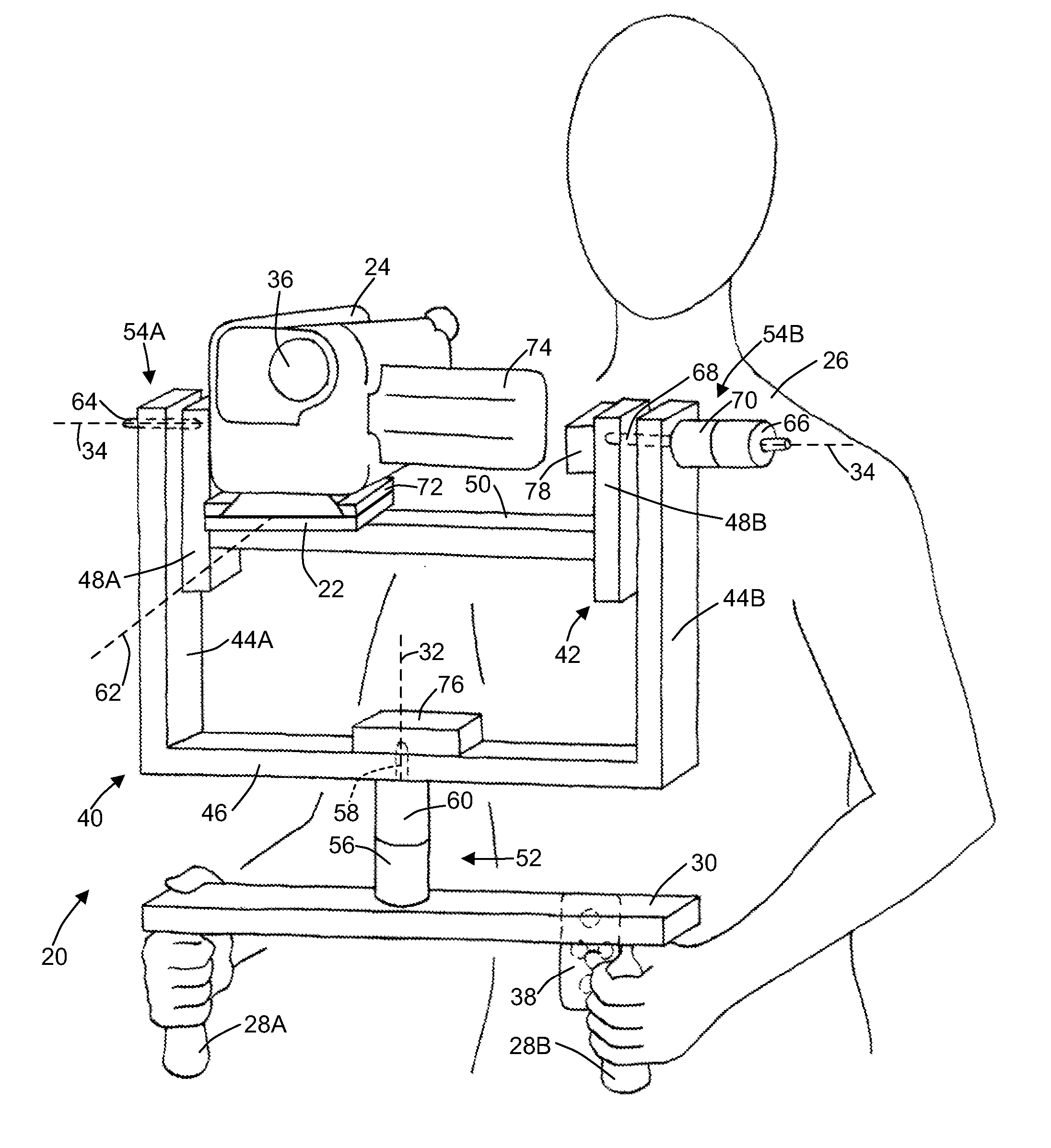
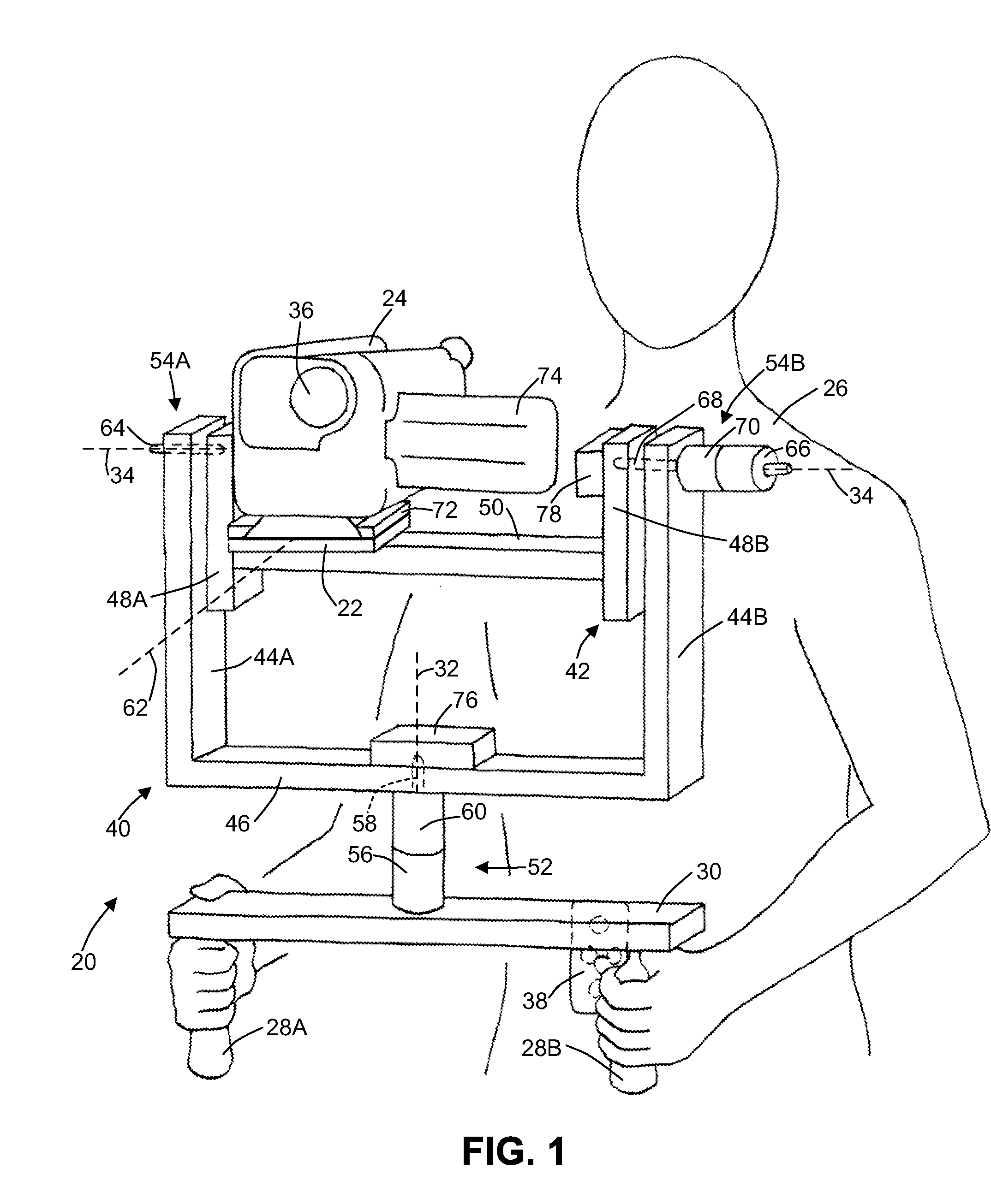
[0069]FIG. 1 illustrates an exemplary camera stabilization system embodiment 20 that stabilizes a platform 22 adapted to support and stabilize, e.g., a camera 24 against all yaw and pitch motion induced by the operator 26 through, e.g., a pair of handles 28A-B attached to a base 30. System 20 provides two orthogonal rotational degrees of freedom about a yaw axis 32 and a pitch axis 34. These degrees of freedom correspond respectively to panning and tilting of camera 24 at platform 22, which together define a center of mass (not shown), also herein denominated centroid or mass centroid. FIG. 1 depicts camera 24 with the camera lens 36 directed generally level and forward. However, system 20 allows panning and / or tilting of camera 24 through a range of over 180 degrees with full stabilization at any orientation. For example, camera lens 36 may be tilted to face vertically upward or nearly vertically downward and may be panned from side to side and around to the rear on either side. As...

embodiment 102

[0089]FIG. 3B is a close-up front view of an alternative pivot assembly embodiment 102 showing the actuator 104 with a rigidly-coupled rotation sensor 106 having a rotation-sensitive sensor axis 108 that is close to but not coincident to the axis of rotation 110 of the pivot motor shaft 112. Preferably, to most accurately determine the true rotational motion of the stabilized platform, rotational sensors should be disposed as close to the associated rotational axis as possible. Especially for gyro sensors that are not completely insensitive to translational motion, the gyro sensor should be disposed close to the associated rotation axis to minimize tangential motion effects at the gyro sensor output and be less sensitive to flexing of the rotationally supported frame

embodiment 114

[0090]FIG. 3C is a close-up front view of another alternative pivot assembly embodiment 114 showing actuator 116 with a rigidly-coupled yaw rotation sensor 118 that is raised by the rigid sensor support 120 above the mounting surface in the direction of the rotation-sensitive sensor axis 122, which is coincident to the axis of rotation of the pivot motor shaft 124. It may be readily appreciated that the teachings of FIG. 3B and 3C apply to any stabilized axis.

[0091] Because the handheld system of this invention and its pitch and yaw frames must be lightweight, they are unavoidably flexible and will bend slightly as the actuators torque them to accelerate the relatively large inertial load of the stabilized camera platform. If the motion sensors are mounted directly to the stabilized camera stage, they must signal the spurious oscillations of the inertial camera stage mass resulting from the excitation of the complex spring-mass mechanical system. High control gains are ordinarily no...


PUM


Abstract

A stabilization system including a platform supported by two or more rotatably-coupled gimbal frames each having a pivot assembly disposed at its rotation axis to couple an actuator to a rotation sensor having a rotation-sensitive sensor axis that is fixedly disposed with respect to the rotation axis, and a controller including means for accepting the sensor signals and for producing each motor signal needed to dispose the platform in a predetermined angular position with respect to each rotation axis independent of changes in the base orientation. A motion simulator embodiment includes controller means for accepting an external slew signal sequence and means for producing the motor signals needed to move the platform along a predetermined sequence of positions represented by the slew signal sequence.

Description

CROSS-REFERENCES TO RELATED APPLICATIONS [0001] This application is made under 37 C.F.R. §1.53(b) claiming the benefit under 35 U.S.C. §119(e) of the provisional Patent Application No. 60 / 675,155 filed on Apr. 27, 2005, now abandoned, which is entirely incorporated herein by reference.BACKGROUND OF THE INVENTION [0002] 1. Field of the Invention [0003] This invention relates generally to camera stabilization systems and more particularly to an inexpensive lightweight handheld camera stabilization system employing distributed gyro rotation sensors to facilitate stabilization over a wide range of camera positions. [0004] 2. Description of the Related Art [0005] Introduction: Advances in optical, video, and traditional photographic technologies have made high quality portable photographic equipment available to a growing number of film enthusiasts. As a result, motion pictures of increased quality and complexity are produced by professionals and enthusiasts alike. However, this quality ...

Claims


Application Information

Patent Timeline
Patent Type & Authority Applications(United States)
IPC IPC(8): G01C21/00
CPCF16M11/041F16M11/048F16M11/18F16M11/2064G03B17/561F16M13/04F16M2200/028F16M2200/044G01C21/18F16M13/00
Inventor SIDMAN, ADAM D.
Owner SIDMAN ADAM D
Why Eureka
Try Eureka