
Electrode base material for fuel cell

a fuel cell and electrode base technology, applied in cell components, acid electrolytes, electrochemical generators, etc., can solve the problems of increased contact resistance and heat loss, difficult to improve and inability to see uniform gas distribution as satisfactory, etc., to achieve uniform gas distribution, reduce contact resistance, and high electrical and thermal conductivities

Inactive Publication Date: 2007-04-12
UBE IND LTD
View PDF5 Cites 7 Cited by
  • Summary
  • Abstract
  • Description
  • Claims
  • Application Information

AI Technical Summary

Benefits of technology

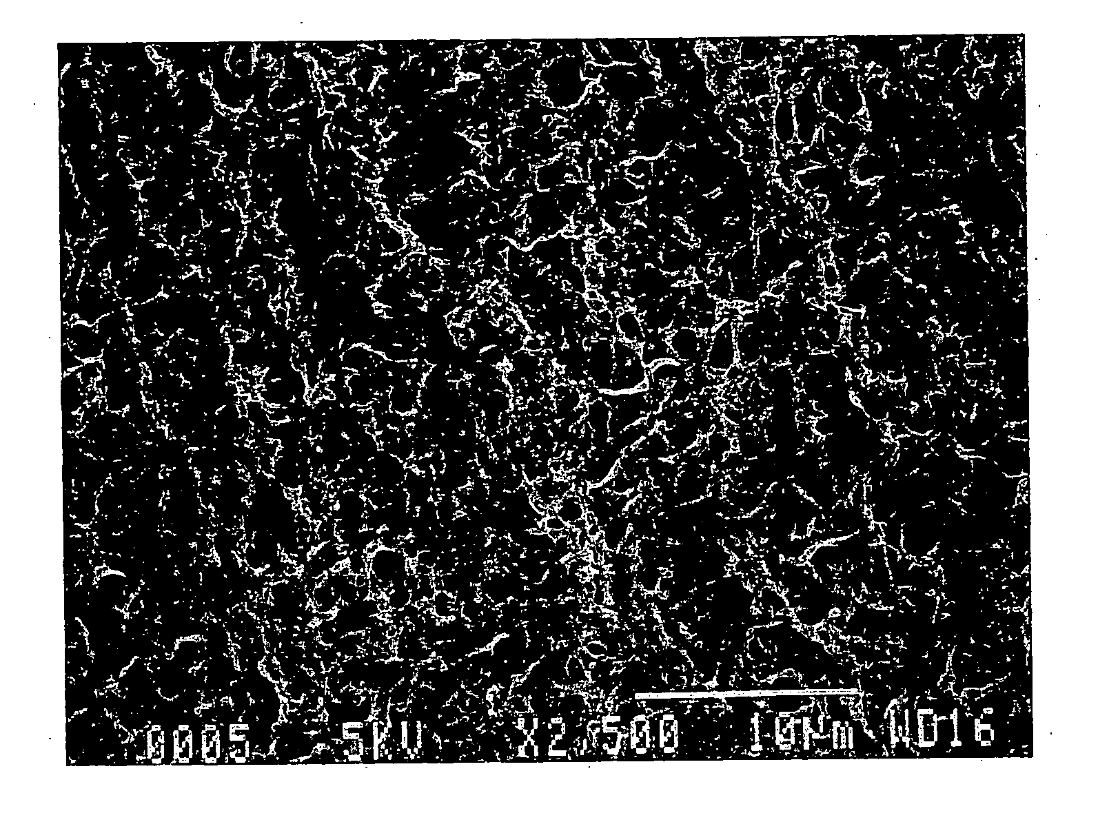
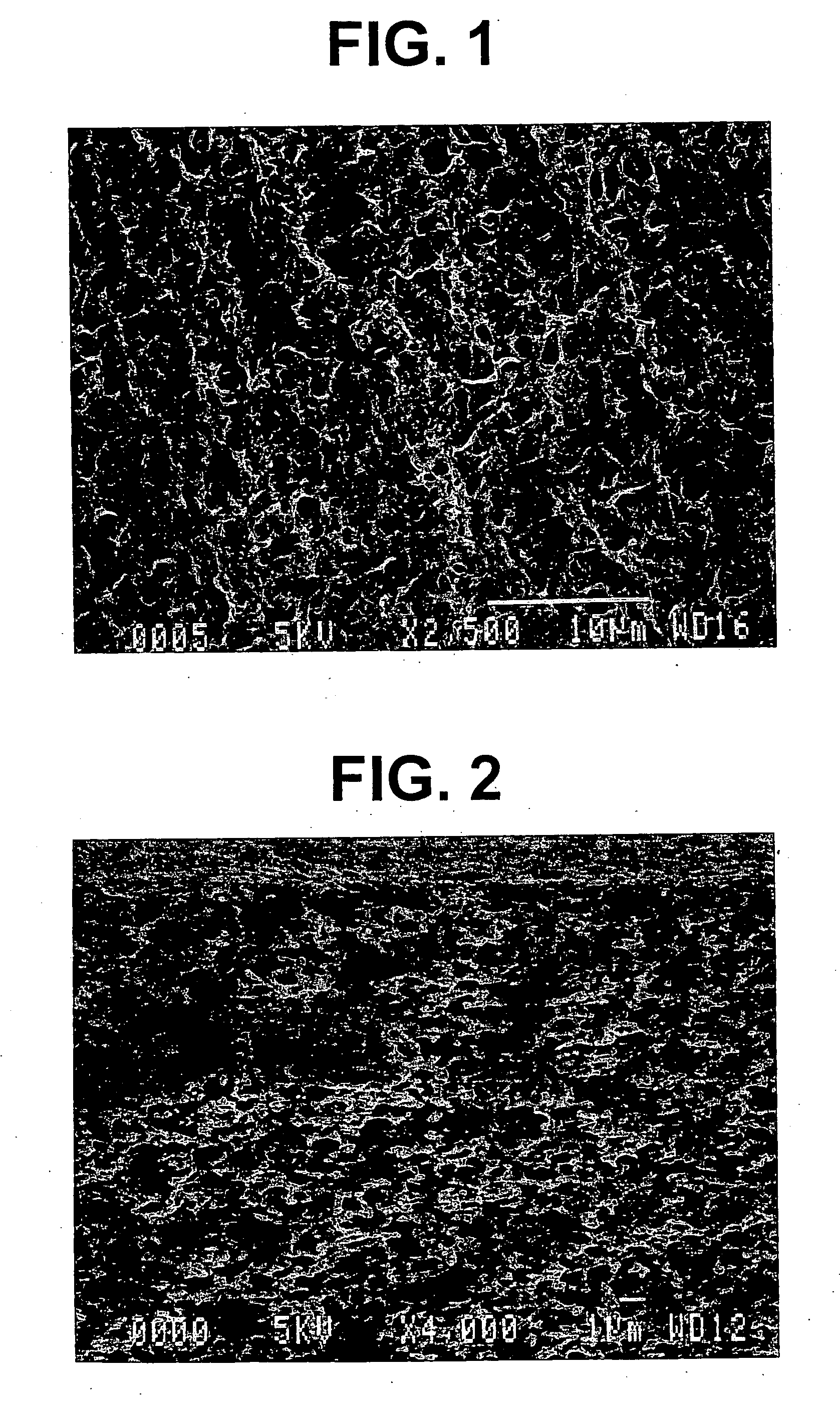
[0010] A first object of the present invention is to provide an electrode base material for fuel cells which is a carbon membranous structure having a porous structure with specific fine interconnecting pores and a smooth surface on both sides thereof except for the pore openings, which is capable of uniform gas distribution over a large area without allowing gas to take a shortcut, which has high electrical and thermal conductivities, and in particular which involves a reduced contact resistance or a reduced heat loss when assembled into a fuel cell.
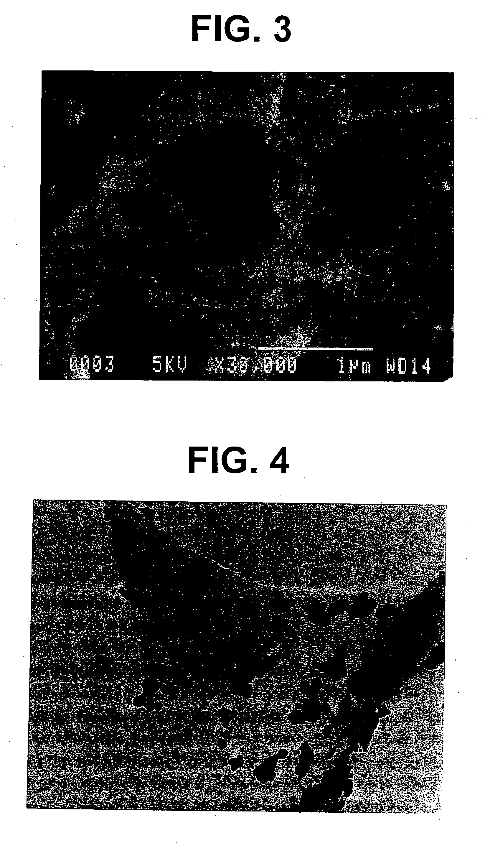
[0011] A second object of the invention is to provide a metal powder-loaded carbon porous structure, particularly an electrode of fuel cells, and to provide an electrolyte membrane-electrode assembly (hereinafter referred to as MEA) having the metal-loaded carbon porous structure which is capable of controlling transport passages for electrons, reactant gases, and protons and will promise high performance to fuel cells.

Problems solved by technology

Therefore, they cannot be seen as satisfactory in uniform gas distribution over a large active area, having liability to allow gas to take a shortcut.
Since carbon fibers in these electrode base materials are in point contact with each other, it is difficult to improve electrical and thermal conductivities.
When the gas diffusion electrode of this type is combined with an electrolyte layer and separators into a unit cell, every interface also has a point contact, resulting in increased contact resistance and heat loss.
However, an electrode base material made up of fine fibers is apt to undergo fiber cutting and fall-off by the reactant gases or drain gas.
Starting with a powdered material, however, structural controllability of an electrode to be prepared is limited, which has made it difficult to fabricate a carrier structure with which an expensive noble metal catalyst can be made effective use of.

Method used


Image

  • Electrode base material for fuel cell
  • Electrode base material for fuel cell
  • Electrode base material for fuel cell

Examples


example 1

Preparation of Polyimide Porous Film:

[0072] 3,3′,4,4′-Biphenyltetracarboxylic acid dianhydride (s-BPDA) as a tetracarboxylic acid component and p-phenylenediamine (PPD) as a diamine component were dissolved in N-metyl-2-pyrrolidone (NMP) at a PPD:s-BPDA molar ratio of 1:0.998 to prepare a monomer solution having a total monomer concentration of 10 wt %. The monomer solution was polymerized at 40° C. for 10 hours to prepare a polyamic acid solution as a polyimide precursor. The polyamic acid solution had a solution viscosity of 7000 P as measured with a cone-plate viscometer at 25° C.

[0073] The polyamic acid solution was cast on a mirror-polished stainless steel plate to a thickness of about 100 μm. The surface of the cast film was covered with a microporous polyolefin film having an air permeance of 550 sec / 100 ml (U-Pore UP2015, available from Ube Industries, Ltd.) as a solvent substitution rate regulating material, taking care not to make wrinkles. The laminate was immersed in ...

example 2

Preparation of Polyimide Porous Film:

[0083] s-BPDA as a tetracarboxylic acid component and PPD as a diamine component were dissolved in NMP at a PPD:s-BPDA molar ratio of 1:0.999 to prepare a monomer solution having a total monomer concentration of 8.5 wt %. The monomer solution was polymerized at 40° C. for 15 hours to prepare a polyamic acid solution as a polyimide precursor. The polyamic acid solution had a solution viscosity of 600 P as measured with a cone-plate viscometer at 25° C.

[0084] The polyamic acid solution was cast on a mirror-polished stainless steel plate to a thickness of about 100 μm. The surface of the cast film was covered with a microporous polyolefin film having an air permeance of 550 sec / 100 ml (U-Pore UP2015, available from Ube Industries, Ltd.) as a solvent substitution rate regulating material, taking care not to form wrinkles. The laminate was immersed in 1-propanol for 7 minutes, whereby the solvents were exchanged via the solvent substitution rate re...

example 3

[0090] Each of the MEAs prepared in Example 2 and Comparative Example 4 was assembled into a fuel cell, and the current-potential characteristics of the cell were measured. As a result, the output at 0.35 V was 80 mA / cm2 and 430 mA / cm2, respectively. These results, converted on the basis of unit platinum loadings, correspond to 4000 A / g (Example 2) and 860 A / g (Comparative Example 4). The apparent activity per unit weight of the platinum catalyst of Example 2 is thus estimated at 4.5 times or more that attained in Comparative Example 4.


PUM

PropertyMeasurementUnit
porosityaaaaaaaaaa
diameteraaaaaaaaaa
sizeaaaaaaaaaa

Abstract

Disclosed are a carbon porous membranous structure having fine interconnecting pores an average diameter of which is 0.05 to 10 μm and a porosity of 15 to 85% and a metal-dispersed carbon structure comprising that carbon porous membranous structure having dispersed therein fine particles of at least one kind of a metal and an alloy. The carbon porous membranous structures are useful as a component of fuel cells, particularly as an electrode base material of gas diffusion electrodes for solid polymer electrolyte fuel cells and phosphoric acid fuel cells.

Description

BACKGROUND OF THE INVENTION [0001] 1. Field of the Invention [0002] The present invention relates to a component of a fuel cell, particularly an electrode base material suitable for making a gas diffusion electrode to be used in fuel cells, such as solid polymer electrolyte fuel cells and phosphoric acid fuel cells, and a fuel cell comprising the base material. [0003] 2. Description of the Related Art [0004] In recent years fuel cells are being developed and put to practical use. The state-of-the-art fuel cells include a solid polymer electrolyte fuel cell comprising a solid polyelectrolyte layer, a gas diffusion electrode made of a porous carbon fiber plate having a thickness of 0.1 to 0.3 mm made by papermaking technology and having a platinum catalyst supported on the surface thereof as an electrode catalyst which is disposed on both sides of the polyelectrolyte layer, and a dense carbon plate having a thickness of 1 to 3 mm and having gas flow channels on its surface which is di...

Claims


Application Information

Patent Timeline
Patent Type & Authority Applications(United States)
IPC IPC(8): H01M4/88H01M4/02H01M4/86H01M4/92H01M4/96H01M8/10
CPCH01M4/8605H01M4/926H01M4/96H01M8/0234H01M8/1004H01M2004/021H01M2300/0008H01M2300/0082Y02E60/50Y02E60/523Y02E60/10
Inventor OHYA, SHYUSEITAKAGI, JUNFUJII, YUUICHIYAO, SHIGERU
Owner UBE IND LTD
Learn More