
Multi-layered thin film hydrogen fuel cell system

a fuel cell and multi-layer technology, applied in the direction of cell components, final product manufacturing, sustainable manufacturing/processing, etc., can solve the problems of high power consumption, difficult to manufacture the reformer first of all, and inability to miniaturize the entire system to the degree usable in a mobile phone, etc., to achieve high-efficiency electricity and facilitate mass production

Inactive Publication Date: 2007-04-19
SAMSUNG ELECTRO MECHANICS CO LTD
View PDF8 Cites 12 Cited by
  • Summary
  • Abstract
  • Description
  • Claims
  • Application Information

AI Technical Summary

Benefits of technology

[0029] Another object of certain embodiments of the invention is to provide a multi-layered thin film hydrogen fuel cell system which has a multi-layered thin film structure integrally combined with a hydrogen-generating reformer using MEMS, using hydrocarbon compound fuel such as methanol, dimethyl, ethylene, or dimethyl-ether (DME) and easily mass-produced, thereby producing high-capacity, high-efficiency electricity.

Problems solved by technology

With the current technology with low efficiency in hydrogen storage, however, miniaturization of the entire system to the degree usable in a mobile phone does not seem feasible.
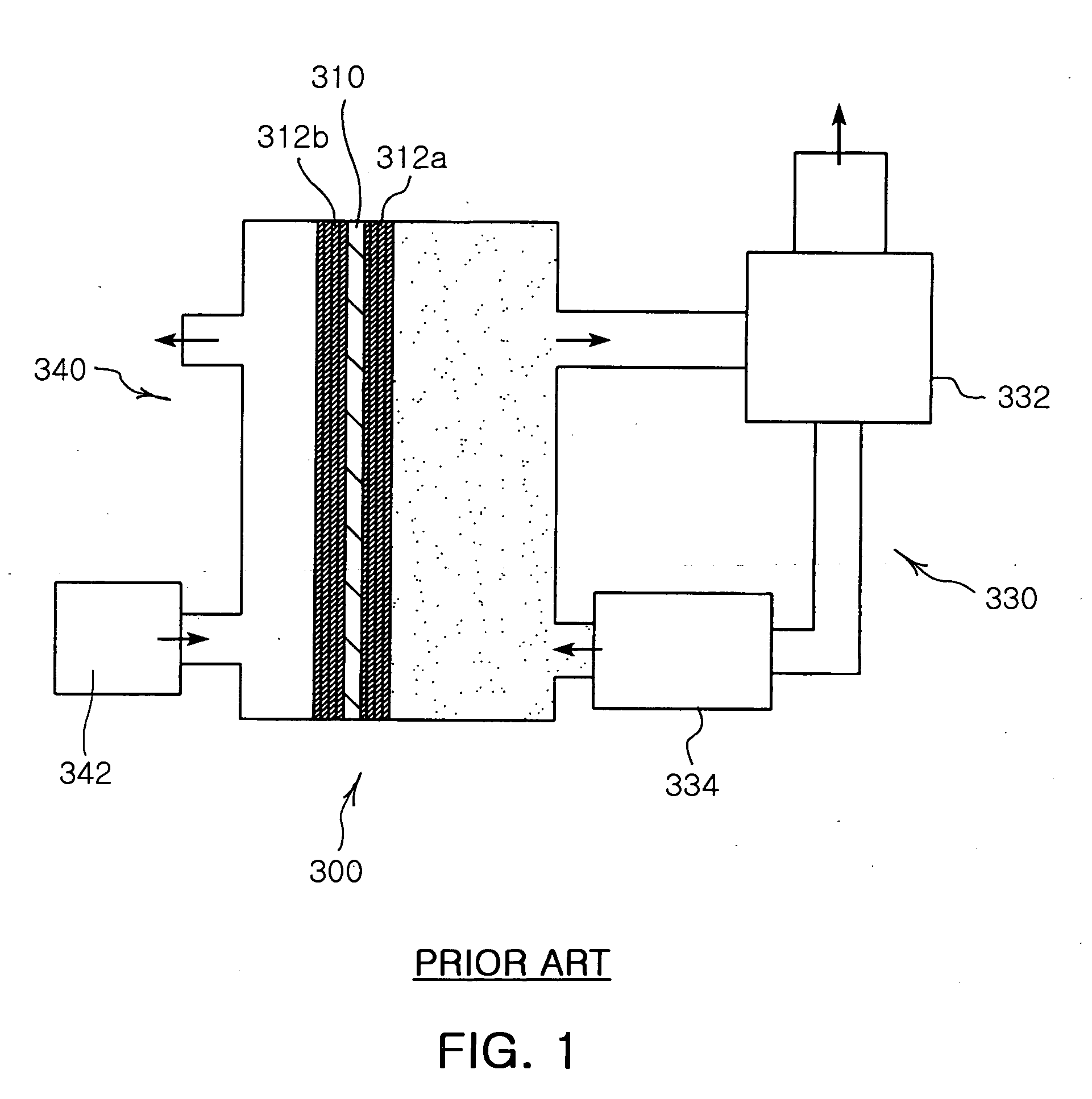
As for the second type, which involves using the reformer to supply hydrogen, it is difficult to manufacture the reformer first of all.
Moreover, the reforming reaction typically requires high temperature of about 200° C. to 300° C., incurring high power consumption.
Also, and the generally used electrolyte membrane such as nafion cannot withstand such high temperature.
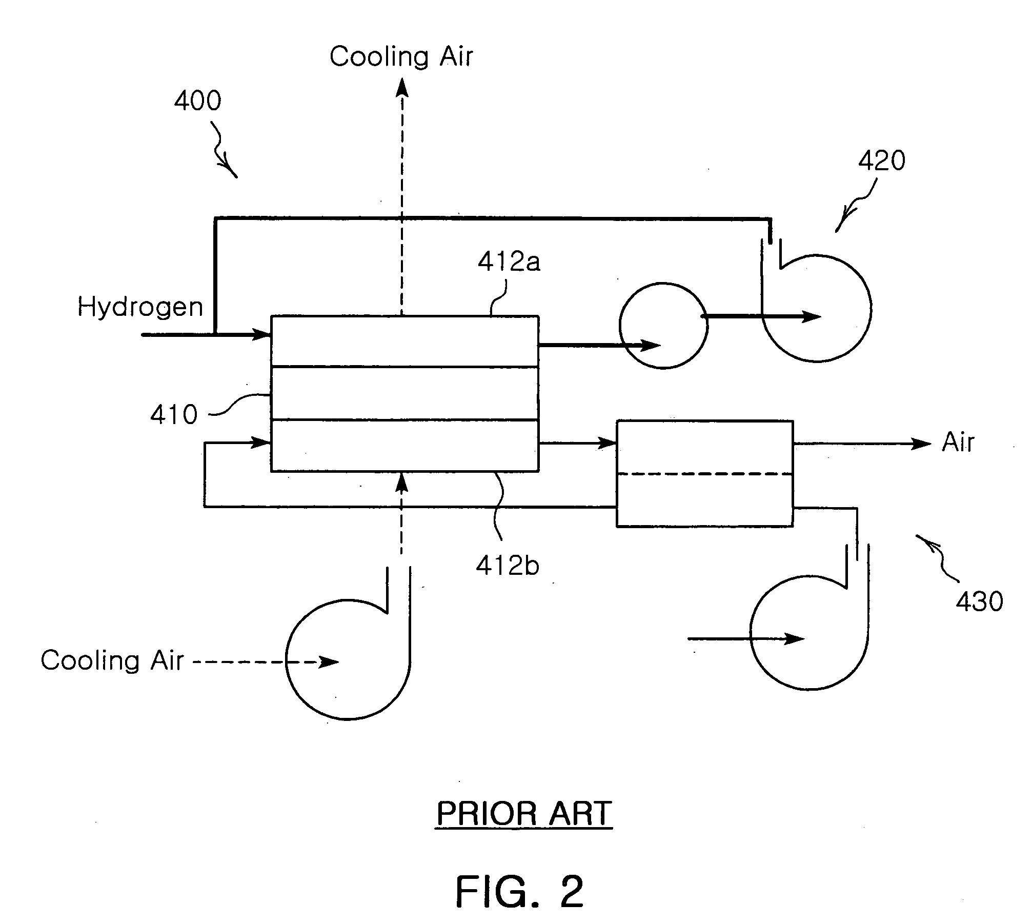
However, the fuel cell 500 is not suitable for miniaturization since it fails to realize an efficient structure such as a stacked structure of thin films.

Method used


Image

  • Multi-layered thin film hydrogen fuel cell system
  • Multi-layered thin film hydrogen fuel cell system
  • Multi-layered thin film hydrogen fuel cell system

Examples


first embodiment

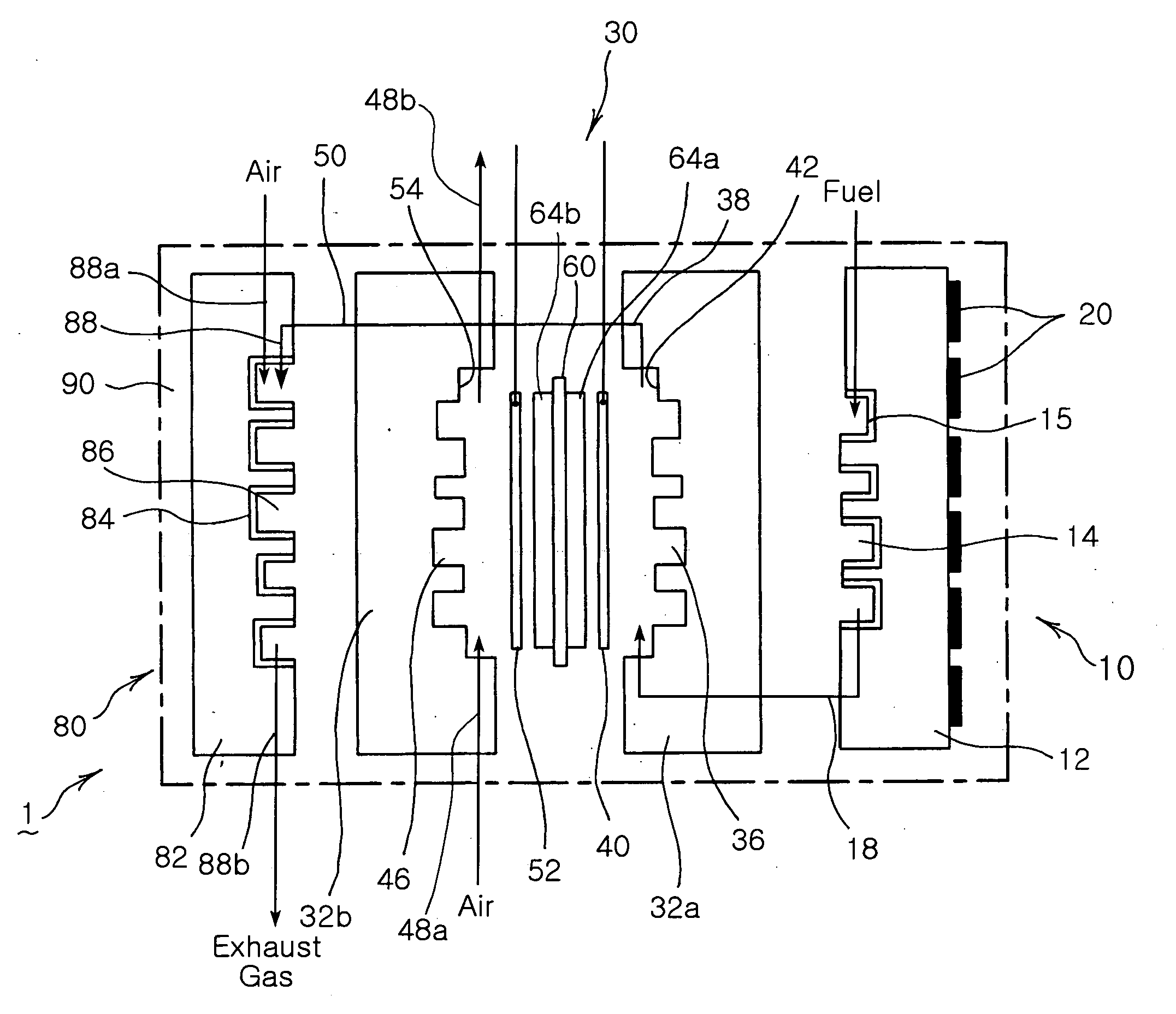
[0082] Thus, in the multi-layered thin film hydrogen fuel cell system 1 with the above described configuration according to the invention, when methanol (CH3OH) and water (H2O) of hydrocarbon compound fuel is supplied through the fuel inlet 16 of the reformer 10 and heated at a reaction temperature ranging from 150° C. to 250° C., a reformation process accompanying heat absorption reaction takes place and thereby hydrogen gas and the small amount of, preferably, less than 2% of CO, water and CO2 is emitted from the reformed gas outlet 18.

[0083] While the reformed gas migrates upward through the reformed gas inlet 34 of the second substrate 32a of the cell 30, it contacts the catalyst layer 64a of the MEA. During this process, hydrogen gas is disintegrated into hydrogen ions (H+) and electrons (e−), of which only the hydrogen ions pass through the MEA 60, and the electrons (e−) migrate through the second current collector 40. Due to the flow of the electrons (e−) at this time, curren...

second embodiment

[0090] FIGS. 12 to 14 illustrate a multi-layered thin film hydrogen fuel cell system according to the invention.

[0091] The multi-layered thin film hydrogen fuel cell 100 according to the second embodiment of the invention includes a reformer having a substrate 112 with a flow path formed on a side thereof and a catalyst formed in the flow path, thereby reforming fuel into hydrogen.

[0092] The reformer 110 is a part for generating hydrogen from fuel, and generally adopts a catalyst 115 of CuO / ZnO / Al2O3 or Cu / ZnO / Al2O3 in the case of methanol steam reformation. The reforming reaction temperature is selected in a range of 150° C. to 250° C. considering the hydrogen conversion rate and CO generation density of 2% or less so that and an MEA is not affected.

[0093] The substrate 112 of the reformer 110 is made of Si. It has a structure similar to that shown in FIG. 7, having a recessed flow path 114 formed in zigzag in a side thereof. The recessed flow path 114 has a fuel inlet 116 formed...


PUM

PropertyMeasurementUnit
temperatureaaaaaaaaaa
depthaaaaaaaaaa

Abstract

The invention relates to a micro multi-layered thin film hydrogen fuel cell system, which includes a reformer comprising a flow path formed at a side of a substrate and a catalyst in the flow path to reform a fuel into hydrogen. The fuel cell system also includes a cell for generating current using the hydrogen from the reformer. The cell comprises a pair of first and second substrates covering the substrate of the reformer with a membrane electrode assembly disposed between the pair of substrates with a catalyst formed thereon. The fuel cell system further includes a combustor for burning remaining fuel gas to generate heat. The combustor comprises a substrate disposed at an outer side of the second substrate of the cell, and a flow path formed in the substrate with a catalyst formed thereon.

Description

CLAIM OF PRIORITY [0001] This application claims the benefit of Korean Patent Application No. 2005-97594 filed on Oct. 17, 2005, in the Korean Intellectual Property Office, the disclosure of which is incorporated herein by reference. BACKGROUND OF THE INVENTION [0002] 1. Field of the Invention [0003] The present invention relates to a micro multi-layered thin film hydrogen fuel cell system, and more particularly, to a multi-layered thin film hydrogen fuel cell system which has a multi-layered thin film structure integrally combined with a hydrogen-generation reformer using Micro-Electro-Mechanical Systems (MEMS), thus using hydrocarbon compound fuel and easily mass-produced, thereby producing high-capacity, high-efficiency electricity. [0004] 2. Description of the Related Art [0005] In general, fuel cells are classified into various types including polymer electrolyte membrane fuel cells, direct methanol fuel cells, molten carbonate fuel cells, solid oxide fuel cells, phosphoric aci...

Claims


Application Information

Patent Timeline
Patent Type & Authority Applications(United States)
IPC IPC(8): H01M8/06H01M8/04H01M8/10H01M2/08
CPCH01M8/0271H01M8/0291H01M8/04022H01M8/04089H01M8/0612H01M8/0662H01M8/1002H01M8/103H01M8/242Y02E60/521H01M8/026H01M8/0263H01M8/0267H01M8/0289H01M8/1007Y02E60/50Y02P70/50H01M8/06
Inventor KIM, SUNG HANKIM, SANG JINLEE, RO WOONGIL, JAE HYOUNGJANG, JAE HYUK
Owner SAMSUNG ELECTRO MECHANICS CO LTD
Learn More