
Cryogenic fluid composition

a technology of cryogenic fluid and composition, applied in the field of machining processes, can solve the problems of cracking and failure of the entire insert along the cutting edge, abrasion between the cutting insert and the workpiece, and the cutting insert of the tool holder

Inactive Publication Date: 2007-05-24
COOL CLEAN TECH
View PDF34 Cites 17 Cited by
  • Summary
  • Abstract
  • Description
  • Claims
  • Application Information

AI Technical Summary

Benefits of technology

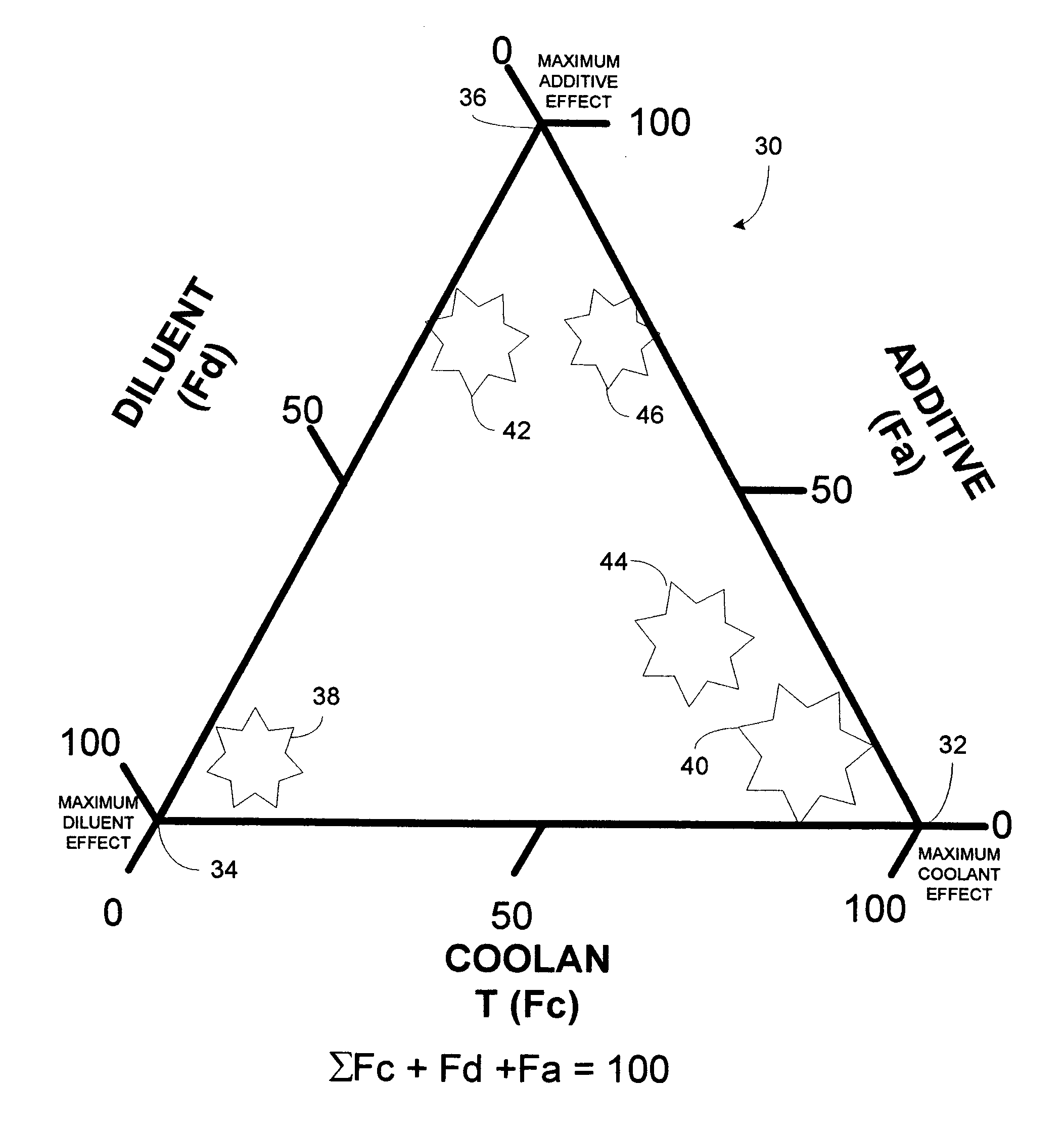
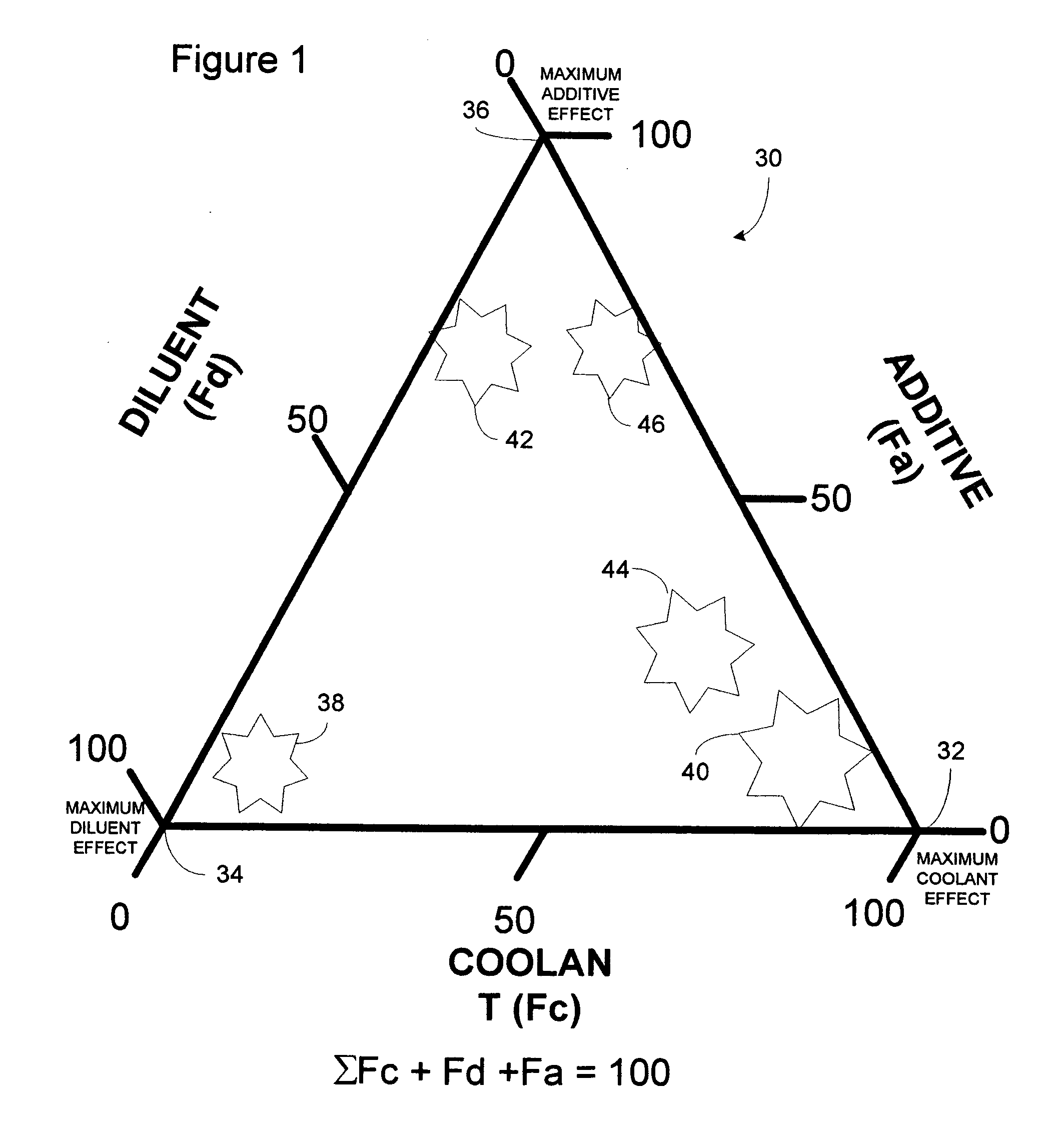
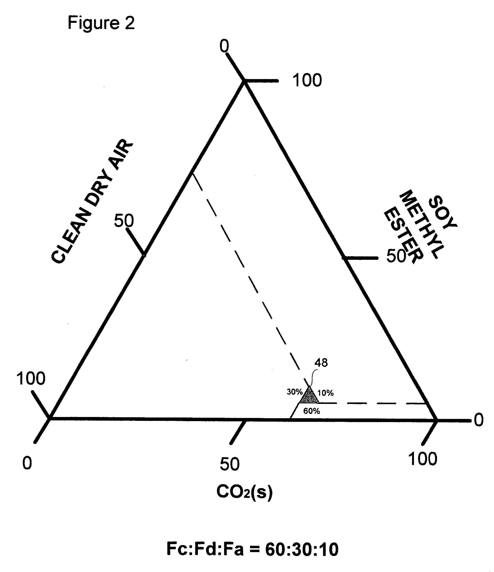
[0017] Numerous single component, binary or ternary coolant-lubricant spray compositions may be derived exhibiting varying physicochemical characteristics such as wetness, dryness, coolness, hotness, pressure, flowrate, lubricity, surface tension, mass, spray film consistency and density. The cryogenic fluid of the present invention can be applied to machining or treatment processes that require selective cleaning, cooling, lubricating or abrasion, including laser machining or treatment operations. The cryogenic fluid composition of the present invention is capable of sweeping away dirt, grime, oils and chips while simultaneously providing cooling and lubrication.

Problems solved by technology

Among the causes of failure of the cutting inserts of tool holders employed in prior art machining operations are abrasion between the cutting insert and workpiece, and a problem known as cratering.
Cratering results from the intense heat developed in the formation of the chips and the frictional engagement of the chips with the cutting insert.
If these craters become deep enough, the entire insert is subject to cracking and failure along its cutting edge, and along the sides of the insert, upon contact with the workpiece.
Cratering has become a particular problem in recent years due to the development and extensive use of hard alloy steels, high strength plastics and composite materials formed of high tensile strength fibers coated with a rigid matrix material such as epoxy.
However, while extremely hard, tungsten carbide inserts are brittle and are subject to chipping which results in premature failure.
The primary problem with flood cooling is that it is ineffective in actually reaching the cutting area.
Again, the problem with the aforementioned apparatuses is that coolant in the form of an oil-water or synthetic mixture, at ambient temperature, is directed across the top surface of the insert toward the cutting area without sufficient velocity to pierce the heat barrier surrounding the cutting area.
As a result, the coolant fails to reach the boundary layer or interface between the cutting insert and workpiece and / or the area on the workpiece where the chips are being formed before becoming vaporized.
In addition, this failure to remove heat from the cutting area creates a significant temperature differential between the cutting edge of the insert which remains hot, and the rear portion of the insert cooled by coolant, causing thermal failure of the insert.
Another serious problem in present day machining operations involves the breakage and removal of chips from the area of the cutting insert, tool holder and the chucks which mount the workpiece and tool holder.
If chips are formed in continuous lengths, they tend to wrap around the tool holder or chucks which almost always leads to tool failure or at least requires periodic interruption of the machining operation to clear the work area of impacted or bundled chips.
This is particularly disadvantageous in flexible manufacturing systems in which the entire machining operation is intended to be completely automated.
Flexible manufacturing systems are designed to operate without human assistance and it substantially limits their efficiency if a worker must regularly clear impacted or bundled chips.
Moreover, environmental health and work safety issues are becoming a major concern.
Since cutting fluids are complex in composition, they may be more toxic than their components and may be an irritant or allergenic even if the raw materials are safe.
Significant negative effects, in terms of environmental, health, and safety consequences, are associated with use of the cutting fluids.
However, as a result, the part being machined has a working surface that contains an inorganic contaminant, water, and an organic contaminant, oil.
This makes the post-cleaning process much more complicated.
However, solvents such as nPB are expensive and pose airborne toxicity issues themselves to exposed workers.
Moreover, reclamation systems and other associated costs of using organic cleaning solvents such as nPB are prohibitively high.
Although generally cheaper and safer to use with respect to organic solvents, these agents themselves become polluted with heavy metals and other contaminants and must be treated prior to disposal.
Another deficiency in the prior art is in regard to the use of dry-cold cryogenic sprays to provide selective mechanical force and cooling within a cutting zone of a laser machining operation.
Although conventional methods of applying cryogenic sprays to a substrate during machining processes, such as spraying liquid carbon dioxide directly onto the machined substrate to form a cold gas-solid aerosol, may be similarly applied to a laser machining surface, these methods and chemistries suffer from several disadvantages.
For example, conventional cryogenic sprays can be used to eliminate laser machining heat and debris, however, because the spray temperature can not be controlled by these conventional processes, significant amounts of atmospheric water vapor is condensed as liquid and solid water in and around the laser cutting zone during the machining operation.
Liquid and solid water present on a cutting surface absorb or reflect strongly in ultra-violet and infra-red spectral regions, which interferes with lasing power and beam delivery onto the substrate surface, thus producing cut quality problems.
Another limitation is that the spray pressures cannot be controlled effectively to balance laser cutting efficiency with fluid force, temperature and pressure.

Method used


Image

  • Cryogenic fluid composition
  • Cryogenic fluid composition
  • Cryogenic fluid composition

Examples


examples

[0081] Several experiments were designed and performed to compare and contrast the relative performance of the present invention against exemplary conventional cooling and lubrication techniques. In the experiments that follow, it should be noted to those skilled in the art that optimum fluid or spray composition parameters such as spray distance, fluid or spray composition, spray angle, spray delivery means, and optimum number of spray delivery devices for a given machining operation were not optimized. The purpose of the experiments was to gage the performance of the composite sprays herein under approximately similar application conditions and replicated machining operations.

High Speed Precision Grinding

[0082] A machining test was performed to examine the machined surface quality and compare this to conventional flooded coolants. The machining process performed was a rough and finish grinding of a stainless steel-steatite-epoxy article having a steatite portion 224, an epoxy p...


PUM


Abstract

A cryogenic fluid composition, and method of forming same, having hyperbaric, lubricating and cooling properties includes selectivity combining a solid phase carbon dioxide, an inert diluent gas and additives in various proportions. The cryogenic machining fluid can be derived by combining a solid carbon dioxide coolant, which may contain or entrain one or more machining lubricant additives, and a diluent phase which is an inert and relatively non-condensing gas phase in various concentrations. The cryogenic fluid composition can be used in cleaning, machining or manufacturing processes to cool, lubricate or ablate a substrate. The cryogenic fluid composition can also be used in conjunction with laser treatment or machining processes without adversely affecting lasing qualities of the laser.

Description

CROSS-REFERENCE TO RELATED APPLICATION(S) [0001] This application claims the benefit U.S. Provisional Patent Application No. 60 / 635,399 filed on 13 Dec. 2004 entitled METHOD, PROCESS, CHEMISTRY AND APPARATUS FOR SELECTIVE THERMAL CONTROL, LUBRICATION AND POST-CLEANING A SUBSTRATE which is incorporated herein by reference. BACKGROUND OF INVENTION [0002] The present invention generally relates to machining processes. More specifically, the present invention relates to machining processes requiring selective thermal control and / or lubrication during lathe machining, board cutting, wafer singulation and active electronic component thermal cycling. The present invention may be used as a metalworking and machining fluid for operations such as turning, milling, facing, threading, boring and grooving, and more particularly, to a method and apparatus for performing such metal working operations at high speeds with extended insert life, and more particularly as a direct replacement for floode...

Claims


Application Information

Patent Timeline
IPC IPC(8): C09K5/00
CPCB23Q11/1053C09K5/041B23Q11/1061
Inventor JACKSON, DAVID P.
Owner COOL CLEAN TECH
Learn More