
Corrosion inhibiting ceramic coating and method of application

a ceramic coating and corrosion inhibitor technology, applied in the direction of superimposed coating process, liquid/solution decomposition chemical coating, manufacturing tools, etc., can solve the problems of increased operating temperature, increased corrosion effect, and insufficient resistance to protect, so as to reduce thermal stress, provide corrosion resistance, and different thermal expansion coefficients

Inactive Publication Date: 2007-06-07
GENERAL ELECTRIC CO
View PDF6 Cites 38 Cited by
  • Summary
  • Abstract
  • Description
  • Claims
  • Application Information

AI Technical Summary

Benefits of technology

"The present invention provides a corrosion-resistant coating for high temperature turbine engine components that are exposed to corrosive environments. The coating is made of a glassy ceramic matrix and particles that provide resistance to corrosion. The coating has a similar coefficient of thermal expansion to the substrate material, reducing thermal stresses and preventing spallation during operation. The coating can be applied to a variety of turbine components, including disks, blade retainers, turbine shafts, and other components that are subjected to high temperatures and corrosive environments. The coating is formed by mixing corrosion-resistant particles with colloidal silica to form a slurry that can be applied to the surface of the component and dried. The resulting coating has a glassy ceramic matrix with uniformly distributed particles that provide resistance to corrosion."

Problems solved by technology

These materials have resistance to oxidation and corrosion damage, but that resistance is not sufficient to protect them at sustained operating temperatures now being reached in gas turbine engines.
Engine components, such as disks and other rotor components, are made from newer generation alloys that contain lower levels of chromium, and can therefore be more susceptible to corrosion attack.
Nevertheless, these components have experienced higher operating temperatures and are experiencing greater corrosion effects as a result of these higher operating temperatures.

Method used


Image

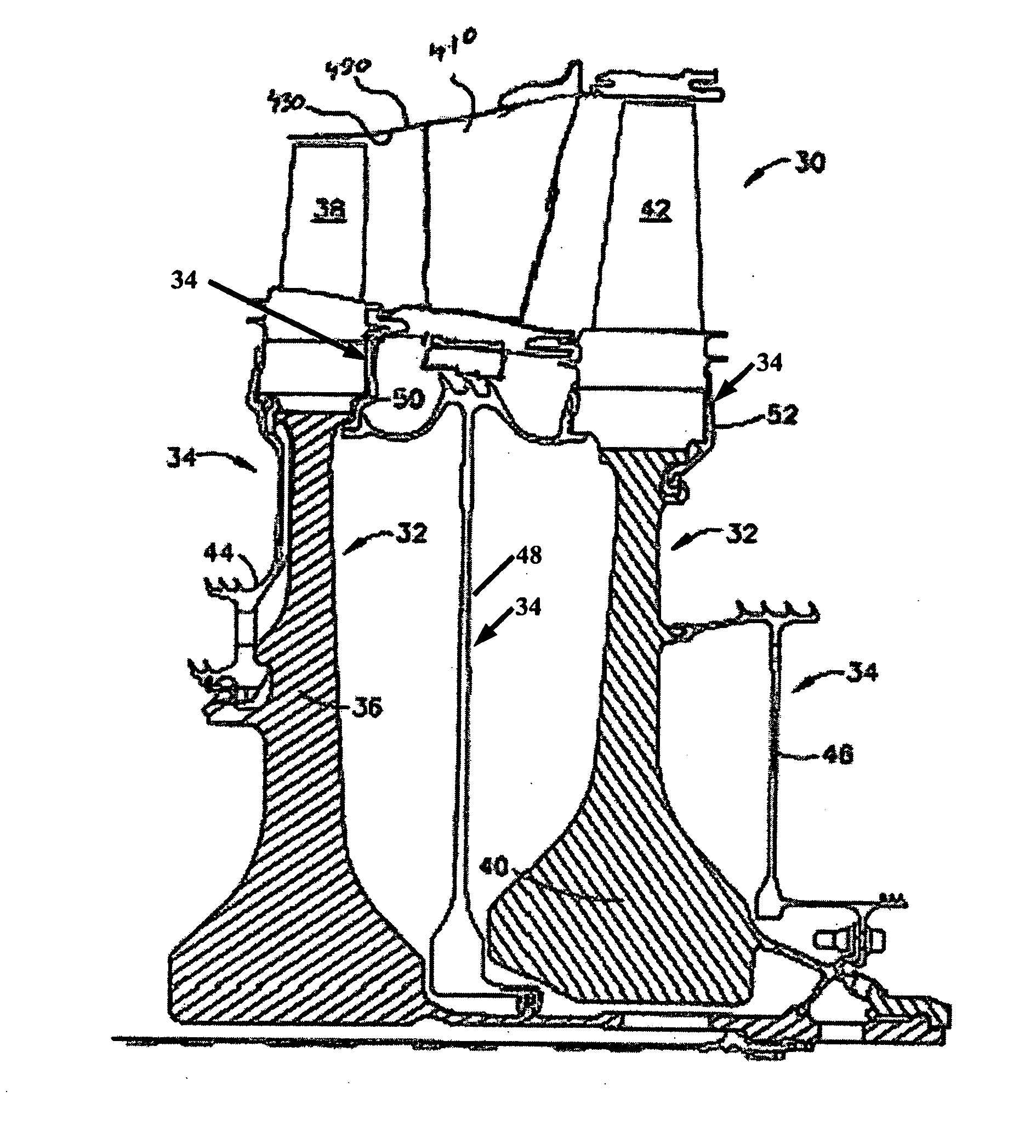
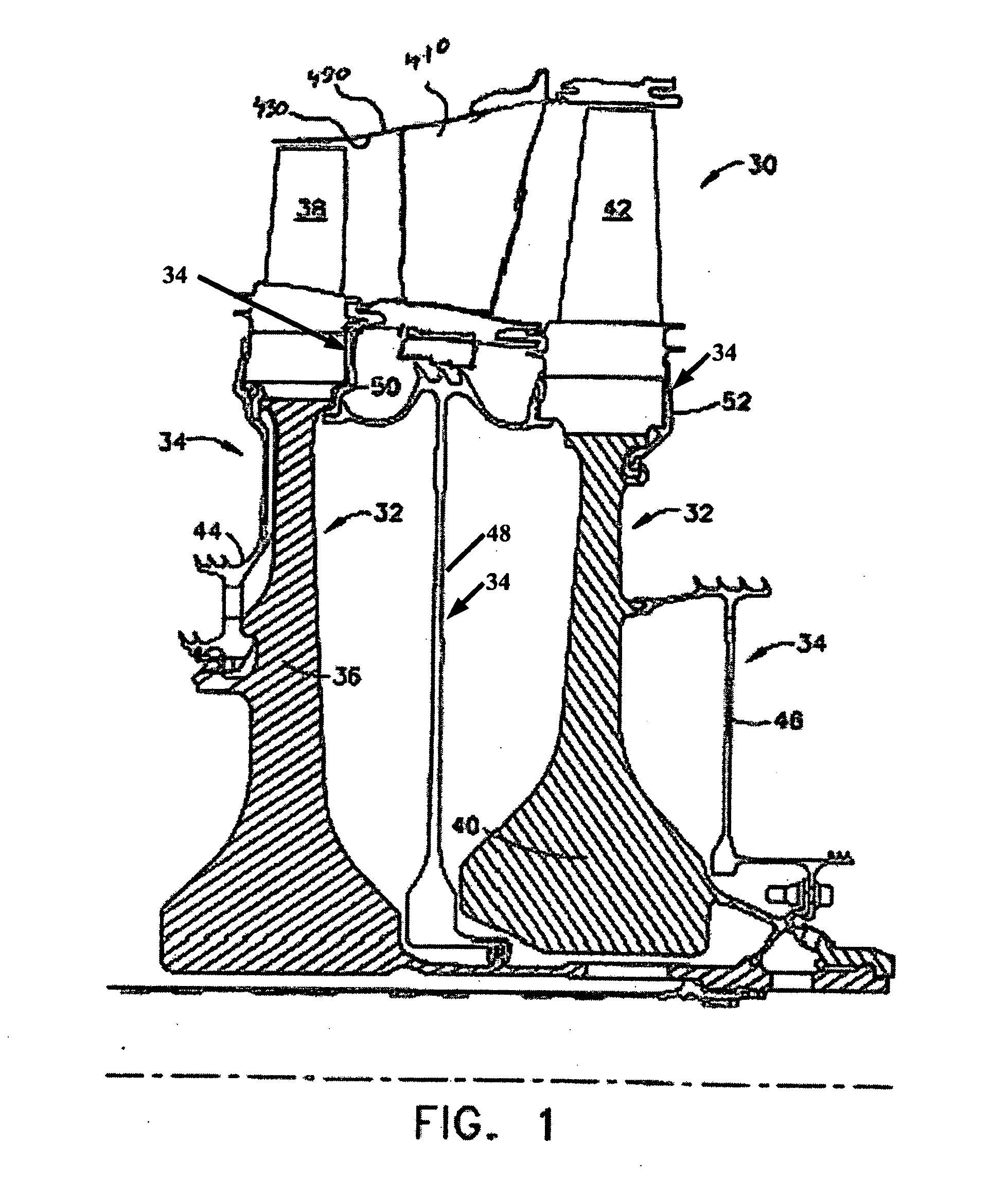
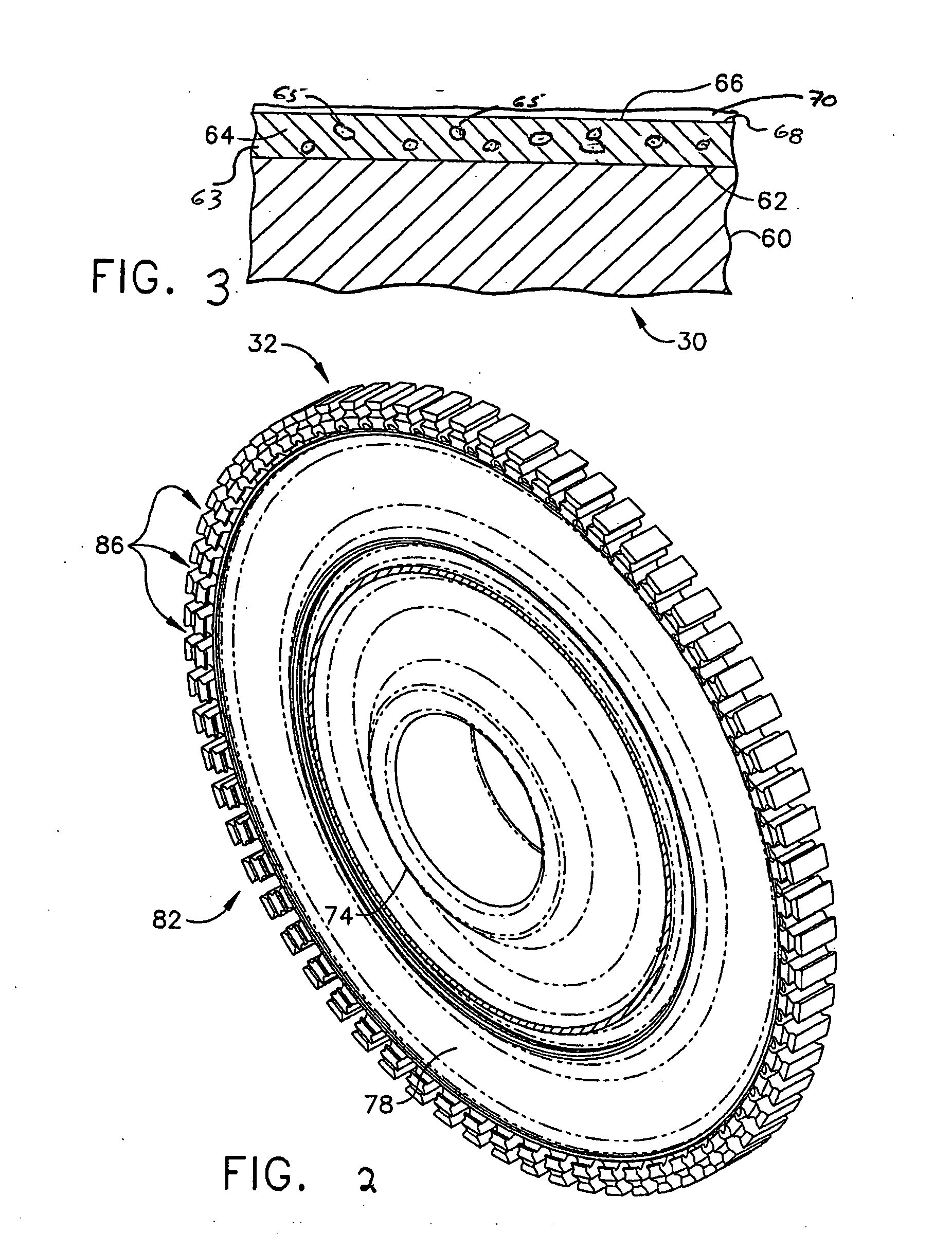
  • Corrosion inhibiting ceramic coating and method of application
  • Corrosion inhibiting ceramic coating and method of application
  • Corrosion inhibiting ceramic coating and method of application

Examples


Embodiment Construction

[0025] The present invention is a corrosion resistant coating applied over a turbine engine component. The corrosion resistant coating comprises refractory oxide particles, MAl, MAlX, MCr, MCrX, MCrAlX particles or a combination thereof, uniformly distributed in a silicon-based matrix. The particles provide the coating with the key corrosion resistance, while the silicon-based material is the binder during application and forms the matrix after curing. On curing, the silicon-based material forms a glassy silicate matrix, which upon firing, may convert at least partially to a glassy ceramic matrix.

[0026] As used herein, the term “corrosion resistant coating” refers to coatings that, after curing of the deposited corrosion resistant coating composition of this invention, comprise at least one layer adjacent to the metal substrate having an amorphous, glassy matrix or glassy-ceramic matrix and having embedded therein, encapsulated therein, enclosed thereby, or otherwise adhered theret...


PUM

PropertyMeasurementUnit
temperatureaaaaaaaaaa

Abstract

A corrosion resistant coating for engine components such as turbine disks, turbine seal elements and turbine shafts. This coating may also find application to other turbine components that are subjected to high temperatures and corrosive environments, such as turbine components located within or on the boundary of the gas fluid flow path, including for example turbine blades, turbine vanes, liners and exhaust flaps. The corrosion resistant coating of the present invention in service on a gas turbine component includes a glassy ceramic matrix wherein the glassy matrix is silica-based and particles selected from the group consisting of refractory oxide particles, MCrAlX particles and combinations of these particles, substantially uniformly distributed within the matrix. The refractory oxide and / or the MCrAlX provides the coating with corrosion resistance. Importantly the coating of the present invention has a coefficient of thermal expansion (CTE) greater than alumina. The CTE of the coating is sufficiently close to the substrate material, that is, the component to which it is applied, such that the coating does not spall after frequent engine cycling at elevated temperature

Description

CROSS REFERENCE TO RELATED APPLICATIONS [0001] This application is related to U.S. patent application Ser. No. 11 / 011695 entitled CORROSION RESISTANT COATING COMPOSITION, COATED TURBINE COMPONENT AND METHOD FOR COATING SAME filed on Dec. 15, 2004, assigned to the assignee of the present application and incorporated herein by reference.FIELD OF THE INVENTION [0002] The present invention is directed to an anti-corrosion coating for use on turbine engine components subjected to moderate temperatures and corrosive environments and methods of applying the coating to turbine engine components. BACKGROUND OF THE INVENTION [0003] In the compressor portion of an aircraft gas turbine engine, atmospheric air is compressed to 10-25 times atmospheric pressure, and adiabatically heated to 800°-1250° F. in the process. This heated and compressed air is directed into a combustor, where it is mixed with fuel. The fuel is ignited, and the combustion process heats the gases to very high temperatures, ...

Claims


Application Information

Patent Timeline
Patent Type & Authority Applications(United States)
IPC IPC(8): B05D3/02B05D1/02
CPCC23C26/00Y02T50/67C23C28/027C23C28/028Y02T50/60
Inventor HAZEL, BRIAN THOMASKOOL, LAWRENCE B.
Owner GENERAL ELECTRIC CO
Learn More