
Apparatus for manufacturing components using electrophoretic deposition

Inactive Publication Date: 2007-06-14
CEREL CERAMIC TECH
View PDF1 Cites 4 Cited by
  • Summary
  • Abstract
  • Description
  • Claims
  • Application Information

AI Technical Summary

Benefits of technology

[0034] The invention described herein provides for a high yield and low cost EPD industrial manufacturing apparatus with efficient materials utilization for the manufacture of small metal and ceramic components, such as anodes of electrolytic capacitors. The invention further provides component shapes and dimensional tolerances not obtained by prior art EPD apparatus.
[0058] c. a physical barrier or masking structure placed near the end of the substrate undergoing electrophoretic deposition, thereby shaping or improving the dimensional tolerance of the end of the component made by EPD deposition on the substrate; and
[0060] In some embodiments of the invention, the substrate fixture covers a part of the substrate, thereby protecting selective areas on the conductive substrates from being exposed to the EPD dispersion. In other embodiments the substrate is contained is a capillary or a tube or a slit which is slightly wider and thicker than the substrate.
[0063] The structures in the EPD cell, which are necessary for structural support or other functions, are preferably made of conductive material and charged to the potential of the counter electrode, thereby reducing deposition of dispersion particles on the structures.
[0065] In some embodiments the recycling cell comprises ultrasonic agitation means to break down agglomerates to their original size distribution. In other embodiments the dispersion in the recycling cell is allowed to undergo sedimentation for a predetermined time in order to remove large agglomerates not compatible with the original particle size distribution and / or excessively fine particles that are not in compliance with the original particle size distribution are removed from the dispersion in the recycling cell. The chemistry of the dispersion fluid in the recycling cell can be corrected by the addition of tiny amounts of chemical additives.

Problems solved by technology

The prior art extensively covers dispersion composition and process parameter requirements for producing components by EPD; however, little innovation is known for the EPD apparatus and deposition system.
Prior art apparatus, such as that shown in FIG. 1, limits the capability of EPD to produce components with very tight dimensional tolerances or monolithic components having unique shapes, such as flat ends and sharp corners.
Furthermore, multiple deposition cycles in such apparatus lead to significant differences in deposited mass between sequential depositions unless the dispersion is replaced frequently, in which case a fresh dispersion might be necessary even for each deposition cycle.
Use of prior art EPD technology for manufacturing monolithic bodies like electrolytic capacitor anodes produces shapes of limited dimensional tolerances.
For laboratory or research purposes, a fresh dispersion can be used for each deposition cycle; however, this is not practical for large scale manufacturing.
By comparison, charge transfer to the deposition electrode cannot be used as a control parameter for mass production by EPD, since most of the electrical charge transferred to the electrode is not carried by the deposited powder particles, but rather by ions from the EPD dispersions.
Prior art EPD technology does not provide methods or apparatus to tightly control deposited mass in subsequent depositions from a given dispersion.

Method used


Image

  • Apparatus for manufacturing components using electrophoretic deposition
  • Apparatus for manufacturing components using electrophoretic deposition
  • Apparatus for manufacturing components using electrophoretic deposition

Examples


example 1

Niobium Oxide Capacitor Anode Manufactured by Fixturing in a Capillary Tube and Immersing in an EPD Cell

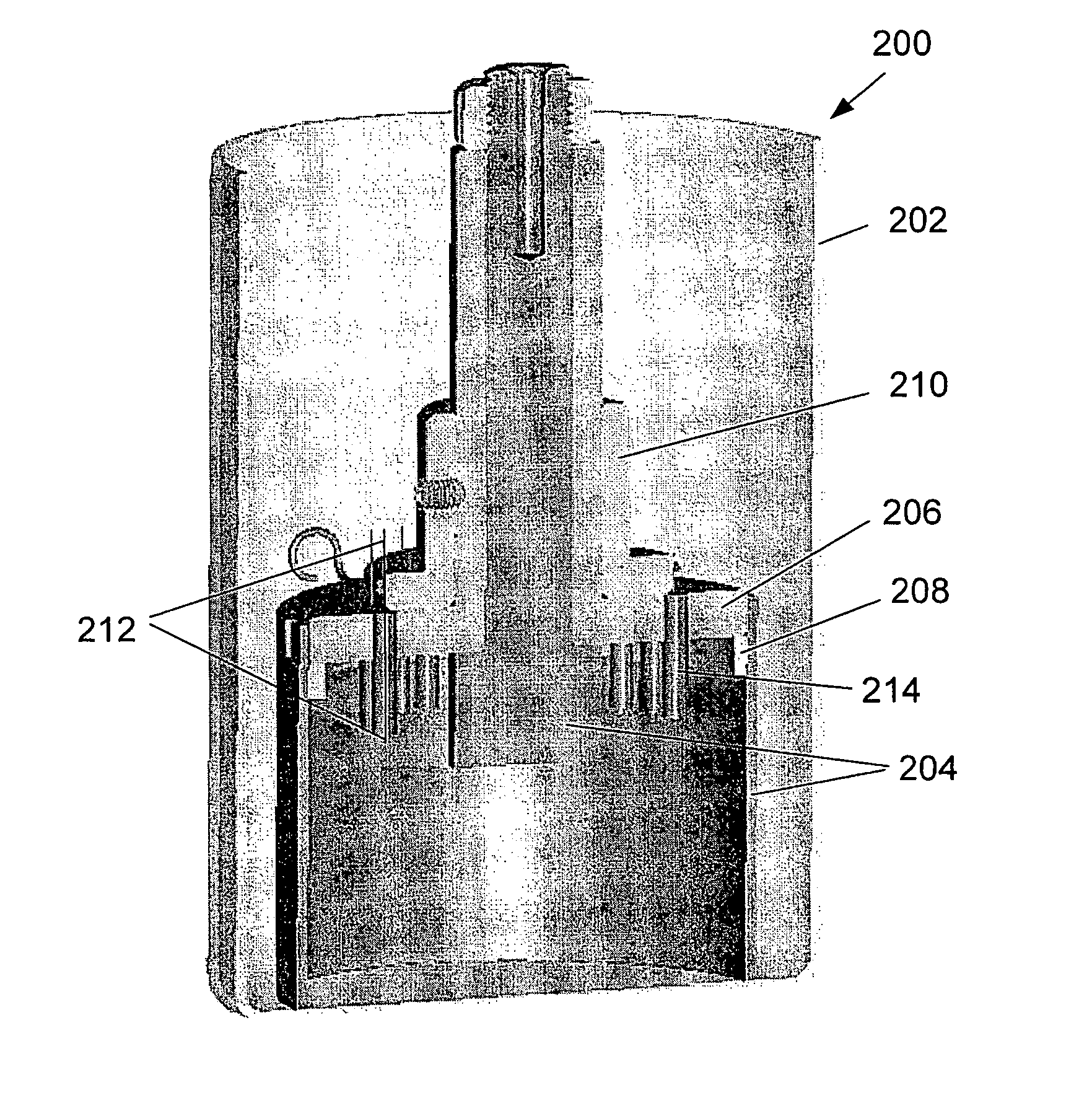
[0132]FIGS. 11A and 11B are optical photographs showing an overall view and longitudinal cross section, respectively, of a green niobium oxide anode as deposited on a tantalum wire by EPD, produced by using a specially designed holder to fix the wire in position in a capillary tube in accordance with one of the embodiments of this invention.

[0133] The dispersion was prepared by dispersing 5 g capacitor grade niobium oxide powder in 100 ml of 2-Propanol. The suspension was subjected to ultrasonic treatment in a Fisher Scientific Sonic Dismembrator 550 at 20 KHz and a power level of 550 Watts for 5 minutes in pulse regime, 2 sec pulse on and 2 sec pulse off. 150 μl of Polyethylenimine 17 wt % aqueous solution was added to the suspension and pulsed sonification repeated for 1 minute. The dispersion was further stirred for 20 minutes. A dispersion pH in the range of 9 to 10 and con...

example 2

Restoring Particle Size Distribution by Agglomerate Sedimentation

[0136] A narrow particle size distribution was produced in niobium oxide dispersion, where the dispersion included large agglomerates. This process applies to both improvement of fresh dispersion by reducing dispersion particle size and narrowing particle distribution, and to restoring particle size distribution of used dispersion where particle size distribution has degraded due to particle agglomeration.

[0137] The niobium oxide dispersion was composed of the following material:

MaterialCatalog No.SupplierBatch No.Niobium Oxide powderNbO-0401Hermann209-2-1(NbO)Starck2-propanol (IPA)16260521BIO LAB40989Polyethylenimine181978Sigma AldrichNA(PEI 17%)

[0138] The equipment used for preparation of the dispersion and its characterization and measurements is as follows:

ApparatusDescriptionSupplierModelSonicatorUsed for particleFisher550 Sonicdispersion by sonic energyScientificdismembratorMastersizerMeasurement of partic...


PUM

PropertyMeasurementUnit
Fractionaaaaaaaaaa
Fractionaaaaaaaaaa
Diameteraaaaaaaaaa

Abstract

The invention is an apparatus, methods and systems for the production of coatings or small components having defined pre-set dimensions and properties by electrophoretic deposition (EPD) on electrically conducting or semi-conducting substrates. The invention provides efficient and precise mass manufacturing of components by EPD, such as anodes of electrolytic capacitors, by achieving high utilization of expensive raw materials and by consistently achieving tight dimensional tolerances of defined component shapes in repeated depositions. This includes production sequences of discrete components, batches of components, and production by semi-continuous operation.

Description

FIELD OF THE INVENTION [0001] The present invention relates to apparatus, methods and systems for applying electrophoretic deposition (EPD) to produce small components and coatings. More specifically, this invention describes a system for manufacturing anodes for solid electrolytic capacitors by electrophoretic deposition (EPD). BACKGROUND OF THE INVENTION [0002] The present invention relates to apparatus, systems and methods for electrophoretic deposition (EPD). Precisely shaped, small metal and ceramic bodies are used in many applications including as anodes for electrolytic capacitors, as pitch bonding capillaries in microelectronics, as high temperature nozzles, as ferrules for connecting optical fibers, as high temperature engine components, as dental crowns, and as bearing parts. To achieve the precise shaping required for some of these applications, like electrolytic capacitor anodes and bonding capillaries, it has been necessary to use the process of pressing to fabricate th...

Claims


Application Information

Patent Timeline
IPC IPC(8): C25D1/12
CPCC25D13/00C25D21/12
Inventor THON, ASSAFBREEN, BARRY NEAL
Owner CEREL CERAMIC TECH
Learn More