Direct-type fuel cell and direct-type fuel cell system

a fuel cell and direct-type technology, applied in the direction of fuel cell details, cell components, electrochemical generators, etc., can solve the problems of large obstacle to the reduction of the size of the fuel cell system, large use of such low concentration fuel, and significant deformation of power generation characteristics, so as to reduce the crossover of fuel and improve the dischargeability of carbon dioxide (reaction product), the effect of suppressing the clogging of the cathode with water

Inactive Publication Date: 2007-06-21
PANASONIC CORP
View PDF8 Cites 12 Cited by
  • Summary
  • Abstract
  • Description
  • Claims
  • Application Information

AI Technical Summary

Problems solved by technology

A first problem is “methanol crossover”, which is a phenomenon in which methanol supplied to the fuel flow channel migrates to the cathode, without reacting, through the electrolyte membrane.
Thus, if the crossover increases, the power generating characteristics degrade significantly.
The use of such low concentration fuel is a large obstacle to the reduction of the size of fuel cell systems.
A second problem is clogging of the cathode with water (flooding) and dry-up of the MEA (dry-up).
Such water clogs the air flow channel due to condensation inside the pores of the cathode.
Thus, when a small amount of air is supplied to the cathode by using a small air pump, blower or the like, the supply of the air is impeded.
As a result, the stability of power generation at high current densities is significantly impaired.
Further, if an excessively large amount of air is supplied, the polymer electrolyte contained in the electrolyte membrane and the catalyst layer of the MEA becomes dry.
As a result, the proton conductivity of the MEA degrades, which may cause a significant deterioration of power generating characteristics.
However, under such operating conditions, it is difficult for the above-mentioned conventional proposals to provide excellent power generating characteristics without lowering fuel utilization efficiency.
Furthermore, if a small amount of a high concentration methanol solution which is very close to the amount consumed by power generation is supplied, the amount of fuel is believed to become insufficient downstream of the fuel flow channel, thereby resulting in a significant deterioration of power generating characteristics.
Hence, the power generating characteristics at high current densities may deteriorate.
Further, Japanese Laid-Open Patent Publication No. 2004-247091 does not propose a specific means for solving the problem of the clogging of the cathode with water which occurs when the air flow rate is lowered.

Method used


Image

  • Direct-type fuel cell and direct-type fuel cell system
  • Direct-type fuel cell and direct-type fuel cell system
  • Direct-type fuel cell and direct-type fuel cell system

Examples


example 1

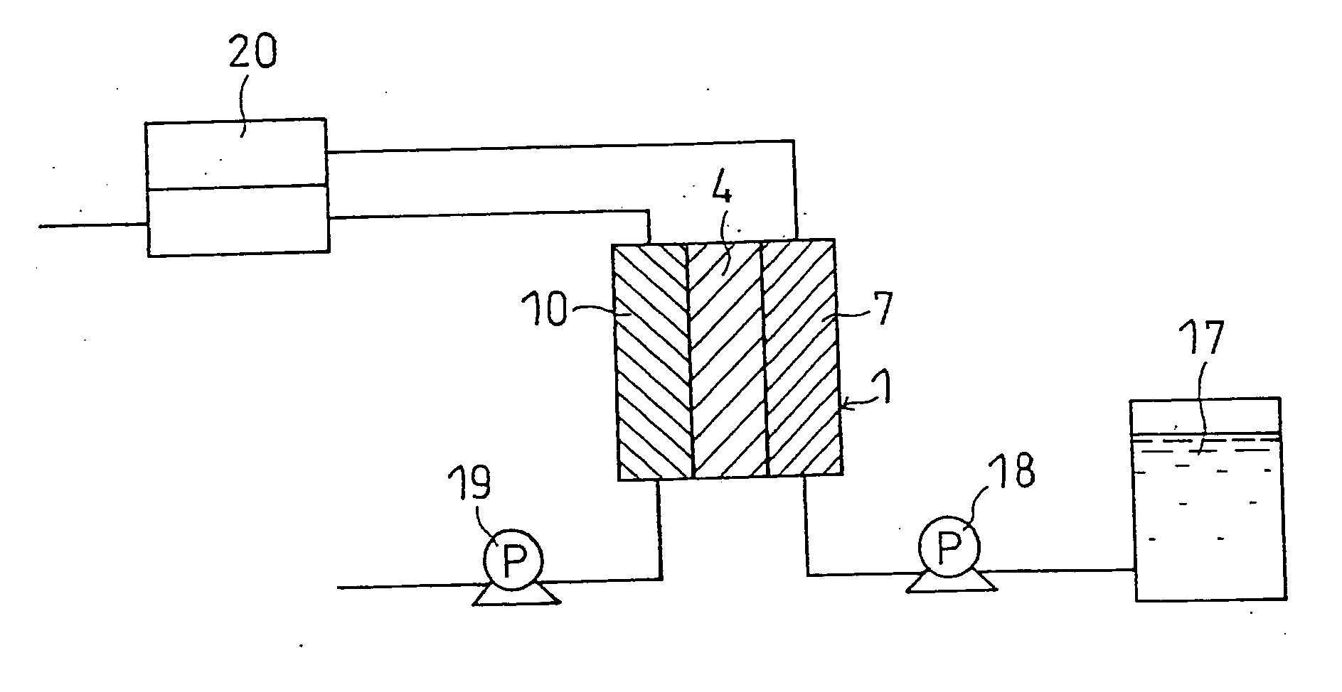
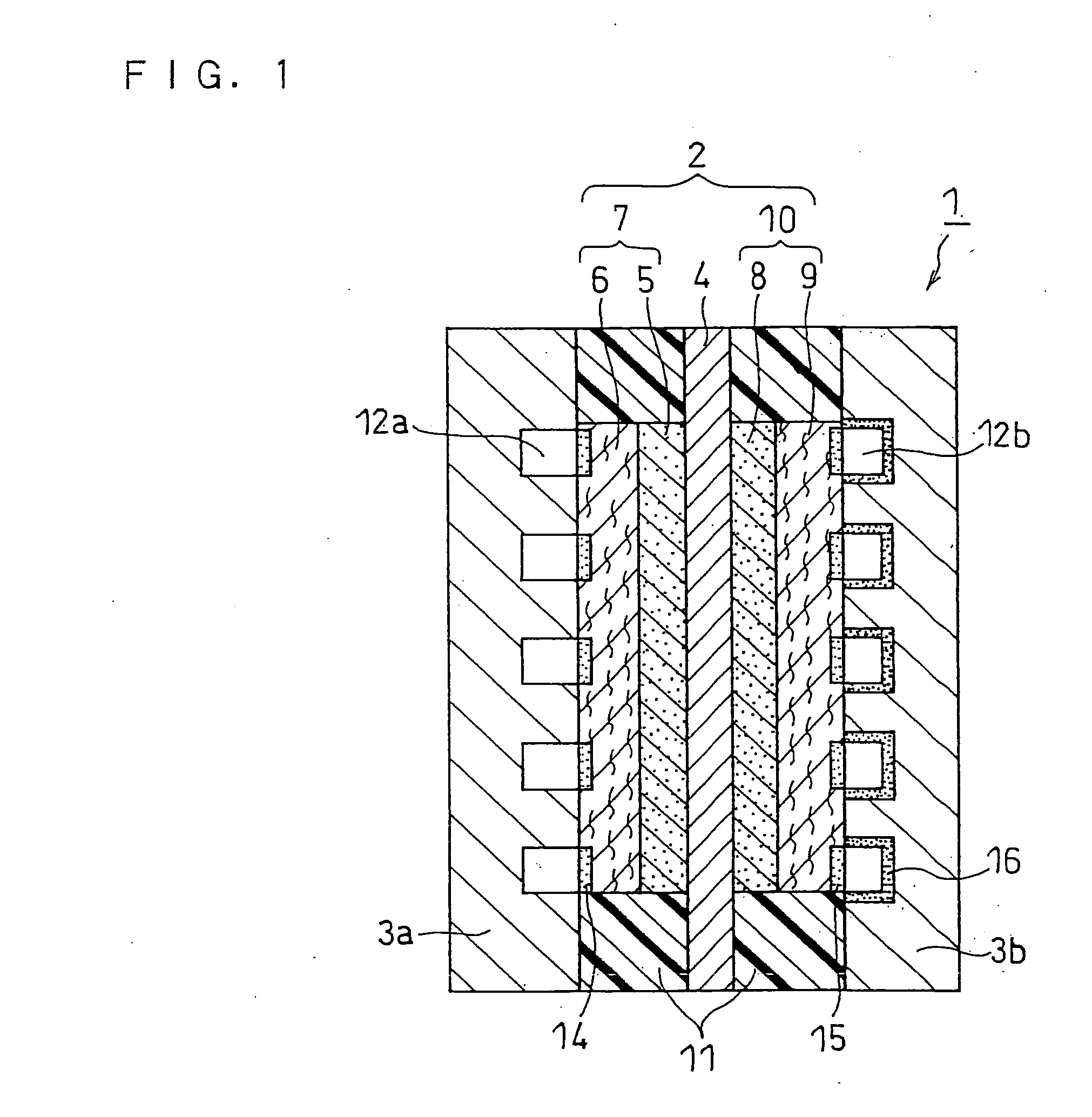
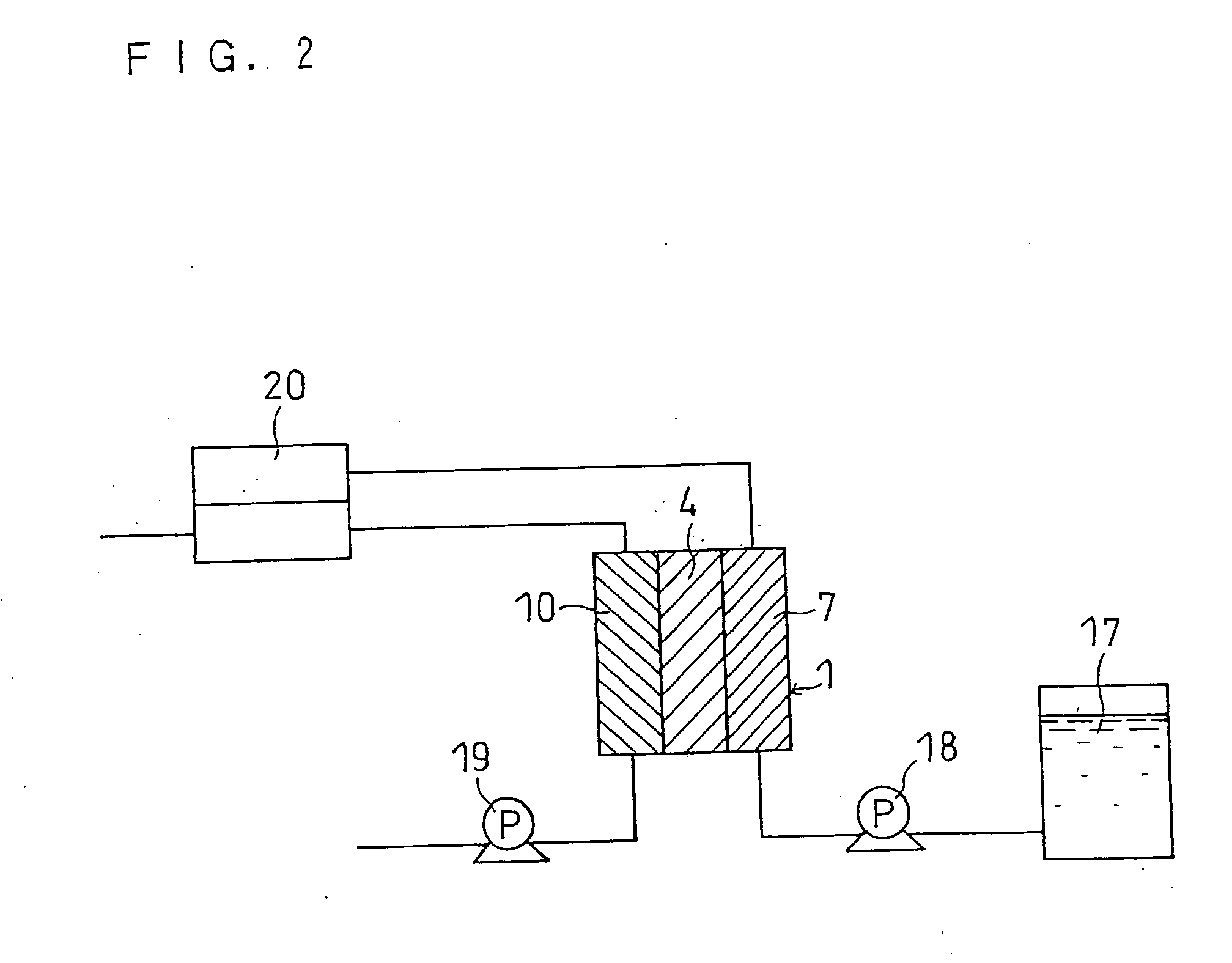
[0085] A fuel cell as illustrated in FIG. 1 was produced.

(i) Anode-Side Catalyst Layer

[0086] Anode-catalyst-carrying particles were prepared by placing 30% by weight of Pt fine particles and 30% by weight of Ru fine particles, both particles having a mean particle size of 3 nm, on carbon black particles with a mean primary particle size of 30 nm (ketjen black EC available from Mitsubishi Chemical Corporation), which are conductive carbon particles.

[0087] A dispersion of the anode-catalyst-carrying particles in an isopropanol aqueous solution was mixed with a dispersion of a polymer electrolyte in an ethanol aqueous solution. This liquid mixture was stirred in a bead mill, to prepare an anode catalyst paste. The weight ratio between the conductive carbon particles and the polymer electrolyte in the anode catalyst paste was 2:1. The polymer electrolyte used was a perfluorocarbon sulfonic acid ionomer (Flemion available from Asahi Glass Co., Ltd.).

[0088] The anode catalyst paste w...

example 2

[0095] In forming the diffusion surface layer 14 (PTFE / silicone layer) on the substrate of the anode-side diffusion layer 6, the repeating number of spray coating and air drying was changed and the high temperature drying condition was changed to 80° C. for 60 minutes in order to make the thickness of the diffusion surface layer 14 to approximately 100 μm. A fuel cell (cell B) was produced in the same manner as in Example 1 except for these changes.

example 3

[0096] A carbon paper with a thickness of 180 μm (TGP-060 available from Toray Industries Inc.) was used as the substrate of the anode-side diffusion layer 6 instead of TGP-H120. Also, in forming the diffusion surface layer 14 (PTFE / silicone layer) on the substrate of the anode side diffusion layer 6, the repeating number of spray coating and air drying was changed and the high temperature drying condition was changed to 70° C. for 20 minutes in order to make the thickness of the diffusion surface layer 14 to approximately 5 μm. A fuel cell (cell C) was produced in the same manner as in Example 1 except for these changes.


PUM

PropertyMeasurementUnit
surface tensionaaaaaaaaaa
contact angleaaaaaaaaaa
energy densityaaaaaaaaaa

Abstract

A direct-type fuel cell having excellent power generating characteristics even under operating conditions utilizing a high concentration fuel at low air flow rates. The anode includes an anode-side diffusion layer that faces the fuel flow channel and an anode-side catalyst layer in contact with the electrolyte membrane. The cathode includes a cathode-side diffusion layer that faces the air flow channel and a cathode-side catalyst layer in contact with the electrolyte membrane. A surface area of the anode-side diffusion layer facing the fuel flow channel or both a surface area of the anode-side diffusion layer facing the fuel flow channel and a surface area of the cathode-side diffusion layer facing the air flow channel have a critical surface tension of penetrating wettability of 22 to 40 mN / m.

Description

FIELD OF THE INVENTION [0001] The present invention relates to a direct-type fuel cell that directly uses fuel without reforming it into hydrogen and to a system including the same. BACKGROUND OF THE INVENTION [0002] Recently, portable small-sized electronic appliances, such as cellular phones, personal digital assistants (PDAs), notebook PCs, and video cameras, have been becoming more and more sophisticated, and the electric power consumed by these appliances and the continuous operating time thereof have been increasing commensurately. To cope with this, the power sources of these appliances are strongly required to have higher energy density. Currently, lithium secondary batteries are mainly used as the power source of these appliances, but it is predicted that the energy density of lithium secondary batteries will reach its limit at about 600 Wh / L around 2006. As an alternative power source to lithium secondary batteries, it is desired to bring fuel cells using a polymer electro...

Claims


Application Information

Patent Timeline
Patent Type & Authority Applications(United States)
IPC IPC(8): H01M4/94H01M8/02
CPCH01M8/0239H01M8/04194H01M8/1009H01M2008/1095Y02E60/523Y02E60/50H01M8/02H01M4/86
Inventor UEDA, HIDEYUKIFUKUDA, SHINSUKEAKIYAMA, TAKASHI
Owner PANASONIC CORP
Why Eureka
Try Eureka